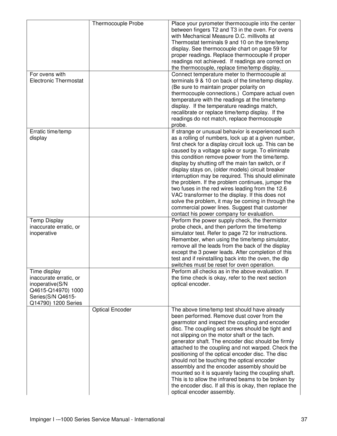
Thermocouple Probe

Place your pyrometer thermocouple into the center


between fingers T2 and T3 in the oven. For ovens


with Mechanical Measure D.C. millivolts at


Thermostat terminals 9 and 10 on the time/temp


display. See thermocouple chart on page 59 for


proper readings. Replace thermocouple if proper


readings not achieved. If readings are correct on


the thermocouple, replace time/temp display.

For ovens with


Connect temperature meter to thermocouple at

Electronic Thermostat


terminals 9 & 10 on back of the time/temp display.


(Be sure to maintain proper polarity on


thermocouple connections.) Compare actual oven


temperature with the readings at the time/temp


display. If the temperature readings match,


recalibrate or replace time/temp display. If the


readings do not match, replace thermocouple


probe.

Erratic time/temp


If strange or unusual behavior is experienced such

display


as a rolling of numbers, lock up at a given number,


first check for a display circuit lock up. This can be


caused by a voltage spike or surge. To eliminate


this condition remove power from the time/temp.


display by shutting off the main fan switch, or if


display stays on, (older models) circuit breaker


interruption may be required. This should eliminate


the problem. If the problem continues, jumper the


two fuses in the red wires leading from the 12.6


VAC transformer to the display. If this does not


solve the problem, it may be coming in through the


commercial power lines. Suggest that customer


contact his power company for evaluation.

Temp Display


Perform the power supply check, the thermistor

inaccurate erratic, or


probe check, and then perform the time/temp

inoperative


simulator test. Refer to page 72 for instructions.


Remember, when using the time/temp simulator,


remove all the leads from the back of the display


except the 3 power leads. After completion of this


test and if reinstalling back into the oven, the dip


switches must be reset for oven operation.

Time display


Perform all checks as in the above evaluation. If

inaccurate erratic, or


the time check is okay, refer to the next section

inoperative(S/N


optical encoder.

Q4615-Q14970) 1000


Series(S/N Q4615-


Q14790) 1200 Series


Optical Encoder

The above time/temp test should have already


been performed. Remove dust cover from the


gearmotor and inspect the coupling and encoder


disc. The coupling set screws should be tight and


not slipping on the motor shaft or the tach.


generator shaft. The encoder disc should be firmly


attached to the coupling and not warped. Check the


positioning of the optical encoder disc. The disc


should not be touching the optical encoder


assembly and the encoder assembly should be


mounted so it is squarely facing the coupling shaft.


This is to allow the infrared beams to be broken by


the encoder disc. If all this is okay, then replace the


optical encoder assembly.

Impinger I -–1000 Series Service Manual - International

37

Page 37
Image 37
Lincoln Series 1200, Series 1000 service manual

Series 1000, Series 1200 specifications

The Lincoln Series 1200 and Series 1000 are two distinguished models in the range of Lincoln Electric welding machines, epitomizing quality, versatility, and advanced technology for both industrial and residential welding applications.

The Lincoln Series 1200 is renowned for its robust build and high-performance capabilities. One of its main features is the ability to perform both MIG (Metal Inert Gas) and stick welding processes, making it a versatile option for various welding requirements. It incorporates an intuitive control panel that allows for easy settings adjustments, ensuring operators can swiftly adapt to different materials and thicknesses. The Series 1200 is equipped with a powerful drive system to provide smooth wire feeding, minimizing downtime due to jams or misfeeds. Additionally, its high-duty cycle support allows continuous operation, making it an ideal choice for professional welders and fabrication shops.

In terms of technology, the Series 1200 employs advanced inverter technology that enhances energy efficiency while reducing the machine’s overall weight. This results in portability without compromising power, making it a practical choice for on-site tasks. Moreover, the machine features an automatic voltage adjustment that optimizes performance based on the input voltage, ensuring reliable operation even under fluctuating power conditions.

On the other hand, the Lincoln Series 1000 is specifically designed for entry-level users and small projects. It shines with its user-friendly interface, which simplifies the welding process for beginners. This model typically includes pre-set parameters and an easy-to-read display, enabling novice operators to achieve excellent welds with minimal experience. Despite its entry-level focus, the Series 1000 does not skimp on performance, offering dependable results across various materials.

Both the Series 1200 and Series 1000 incorporate safety features, including thermal overload protection, ensuring that users can operate the machines with peace of mind. Their durable construction allows for prolonged use in tough work environments without sacrificing reliability.

In conclusion, the Lincoln Series 1200 and Series 1000 cater to a wide range of welding needs, from professional applications to home projects. Their respective features and technologies present options that can fit various skill levels while delivering exceptional welding performance and longevity. Whether you are a seasoned professional or a hobbyist, Lincoln Electric provides reliable solutions to meet your welding requirements.