Lincoln Series 1200 Sequence of Operations 1028 / 1029 / 1228, Heat Circuit, Temperature, Control

Models: Series 1000 Series 1200

1 112
Download 112 pages 35.42 Kb
Page 5
Image 5


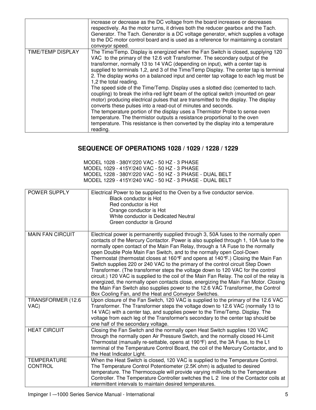
increase or decrease as the DC voltage from the board increases or decreases


respectively. As the motor turns, it drives both the reducer gearbox and the Tach.


Generator. The Tach. Generator is a DC voltage generator, which supplies a voltage


to the DC motor control board and is used as a reference for maintaining a constant


conveyor speed.

TlME/TEMP DISPLAY

The Time/Temp. Display is energized when the Fan Switch is closed, supplying 120


VAC to the primary of the 12.6 volt Transformer. The secondary output of the


transformer, normally 13 to 14 VAC (depending on input), with a center tap is


supplied to terminals 1,2, and 3 of the Time/Temp Display. The center tap is terminal


2. The display works on a balanced input and center tap voltage to each leg must be


1,2 the total reading.


The speed side of the Time/Temp. Display uses a slotted disc (cemented to tach.


coupling) to break the infra-red light beam of the optical switch (mounted on gear


motor) producing electrical pulses that are transmitted to the display. The display


converts these pulses into a read-out of minutes and seconds.


The temperature portion of the display uses a Thermistor Probe to sense oven


temperature. The thermistor outputs a resistance proportional to the oven


temperature. This resistance is then converted by the display into a temperature


reading.

SEQUENCE OF OPERATIONS 1028 / 1029 / 1228 / 1229

MODEL 1028 - 380Y/220 VAC - 50 HZ - 3 PHASE

MODEL 1029 - 415Y/240 VAC - 50 HZ - 3 PHASE

MODEL 1228 - 380Y/220 VAC - 50 HZ - 3 PHASE - DUAL BELT

MODEL 1229 - 415Y/240 VAC - 50 HZ - 3 PHASE - DUAL BELT

POWER SUPPLY

Electrical Power to be supplied to the Oven by a five conductor service.


Black conductor is Hot


Red conductor is Hot


Orange conductor is Hot


White conductor is Dedicated Neutral


Green conductor is Ground


MAIN FAN CIRCUIT

Electrical power is permanently supplied through 3, 50A fuses to the normally open


contacts of the Mercury Contactor. Power is also supplied through 1, 10A fuse to the


normally open contact of the Main Fan Relay, through a 1A Fuse to the normally


open Double Pole Main Fan Switch, and to the normally open Cool-Down


Thermostat (thermostat closes at 160°F and opens at 140°F.) Closing the Main Fan


Switch supplies 220 or 240 VAC to the primary of the control circuit Step Down


Transformer. (The transformer steps the voltage down to 120 VAC for the control


circuit.) 120 VAC is supplied to the coil of the Main Fan Relay. The coil of the relay is


energized, the normally open contacts close, energizing the Main Fan Motor. Closing


the Main Fan Switch also supplies power to the 12.6 VAC Transformer, the Control


Box Cooling Fan, and the Heat and Conveyor Switches.

TRANSFORMER (12.6

Upon closure of the Fan Switch, 120 VAC is supplied to the primary of the 12.6 VAC

VAC)

Transformer. The Transformer steps the voltage down to 12.6 VAC (normally 13 to


14 VAC) with a center tap, and supplies power to the Time/Temp. Display. The


voltage from each leg of the Transformer©s secondary to the center tap should be


one half of the secondary voltage.

HEAT CIRCUIT

Closing the Fan Switch and the normally open Heat Switch supplies 120 VAC


through the normally open Air Pressure Switch, and the normally closed Hi-Limit


Thermostat (manually re-settable, opens at 190°F) and, the 3A Fuse, to the L1


terminal of the Temperature Control Board, the coil of the Mercury Contactor, and to


the Heat Indicator Light.

TEMPERATURE

When the Heat Switch is closed, 120 VAC is supplied to the Temperature Control.

CONTROL

The Temperature Control Potentiometer (2.5K ohm) is adjusted to desired


temperature. The Thermocouple will provide varying millivolts to the Temperature


Controller. The Temperature Controller switches the L 2 line of the Contactor coils at


intermittent intervals to maintain desired temperatures.

Impinger I -–1000 Series Service Manual - International

5

Page 5
Image 5
Lincoln Series 1200, Series 1000 Sequence of Operations 1028 / 1029 / 1228, Heat Circuit, Temperature, Control

Series 1000, Series 1200 specifications

The Lincoln Series 1200 and Series 1000 are two distinguished models in the range of Lincoln Electric welding machines, epitomizing quality, versatility, and advanced technology for both industrial and residential welding applications.

The Lincoln Series 1200 is renowned for its robust build and high-performance capabilities. One of its main features is the ability to perform both MIG (Metal Inert Gas) and stick welding processes, making it a versatile option for various welding requirements. It incorporates an intuitive control panel that allows for easy settings adjustments, ensuring operators can swiftly adapt to different materials and thicknesses. The Series 1200 is equipped with a powerful drive system to provide smooth wire feeding, minimizing downtime due to jams or misfeeds. Additionally, its high-duty cycle support allows continuous operation, making it an ideal choice for professional welders and fabrication shops.

In terms of technology, the Series 1200 employs advanced inverter technology that enhances energy efficiency while reducing the machine’s overall weight. This results in portability without compromising power, making it a practical choice for on-site tasks. Moreover, the machine features an automatic voltage adjustment that optimizes performance based on the input voltage, ensuring reliable operation even under fluctuating power conditions.

On the other hand, the Lincoln Series 1000 is specifically designed for entry-level users and small projects. It shines with its user-friendly interface, which simplifies the welding process for beginners. This model typically includes pre-set parameters and an easy-to-read display, enabling novice operators to achieve excellent welds with minimal experience. Despite its entry-level focus, the Series 1000 does not skimp on performance, offering dependable results across various materials.

Both the Series 1200 and Series 1000 incorporate safety features, including thermal overload protection, ensuring that users can operate the machines with peace of mind. Their durable construction allows for prolonged use in tough work environments without sacrificing reliability.

In conclusion, the Lincoln Series 1200 and Series 1000 cater to a wide range of welding needs, from professional applications to home projects. Their respective features and technologies present options that can fit various skill levels while delivering exceptional welding performance and longevity. Whether you are a seasoned professional or a hobbyist, Lincoln Electric provides reliable solutions to meet your welding requirements.