COMMANDER 500

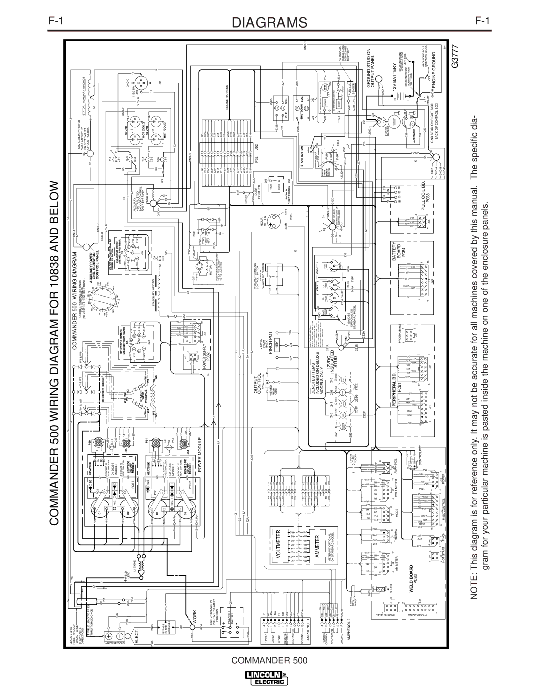
COMMANDER 500 WIRING DIAGRAM FOR 10838 AND BELOW


6A


6A


6A


LEADS 3 & 6A


3


3


COMMANDER 500 WIRING DIAGRAM


3


3


PASS THROUGH


GND-F


TOROID TWICE


5A


120V AUXILIARY POWER


IN OPPOSITE


W4 & W5


W2 & W3


W1 & W6


CORRESPONDING SETTINGS


DIRECTIONS


FOR TAP NUMBERS


6A

"INSULATED STUD"


STATOR

AUXILIARY WINDINGS


+WELD LEAD TO PASS


(AS VIEWED FROM THE FRONT)


ON BOTTOM LEFT


P50


200A

350A


OF CONTROL BOX


D3

HEATSINK


AUXILIARY POWER


6D


6


3


THRU TOROID ONCE


150A

11

12


1 500A


6A


POS.


+


B1


3

2

1


10


GND. SCREW ON


5A


5


CONTROL PANEL


GND-C


C1


POS


B2


6 5 4


90A

9


2

STICK


260


3


W7


B3


30-575A


GND-D


9 8

7


RECTIFIER BRIDGE


261


B7


WIRE


50MV=400AMPS

+I


NEG.


1 2 3

18


(VIEWEDFROM REAR)


8


3

TIG


GND-E


31


3A


GND-E


HEAT SINK CONN.


14 TO 40V


PC BOARD TO


250


HEAT SINK CONN.


20-250A


OLDER MACHINES MAY BE


20A


D1 DIODE


TS1


EMPTY


EMPTY


WIRED AS SHOWN:


9


NEG.


MODULE


249


31


204S


EMPTY

EMPTY


SELECTOR SWITCH


CB1


17


(VIEWED FROM REAR)


PC BOARD TO


SELECTOR SWITCH


NEG.


S5


+WELD


206S


J50

4 5 6


W3 W2


S5


217

6 5


216


50A


SILVER


5B


GND-C


260A


LEAD


C2


W8

LEFTSIDE


7 8 9

23


W3


W2


218

7

4

215


3


11


261A


300 AMP


217

12 11


216


6A


J12


+


PCB 6


MODULE


25


218

1


10

215


8

A

3

214


115/230V


11

ELECT.


L1 CHOKE


POS.


AUXILIARY


3


CB3


220

9

2

213


NEUTRAL STUD


GND-D

J10


2


C1

9

214


STATOR


BACK OF CONTROL


222


9


WELD


220

3


8

213


BOX "LEFT SIDE"


20A


HOT (GOLD)


W4


W1


D4


P51


WINDINGS


GND-G


SILVER


HEATSINK


W4


W1


222


8


5E


206A

206B


POS.


+


B1


3 2 1


W5


W6


STATOR 42V WINDING


10A


GND-F


CB2


J11


12


C3


POS


W9


B2


6

5

4


W5


W6


6B


5


50A


B3


9 8 7


42


GND-H


5C


B7


6D


BYPASS


NEG.


PC BOARD TO


249


CB6


5E


6A


8

HOT (GOLD)


GND-K


42A


5B


CB4


FILTER


HEAT SINK CONN.


41


ASSEMBLY


D2 DIODE


TS2


5C


NEG.


MODULE


251


5


14

14A


12


208


HEAT SINK CONN.


1 2 3

15


16


101A

18

116A

118A


16


NEG.


PC BOARD TO


C4


RIGHT SIDE


4 5 6

23A


J41


105A


115A

41A


W10

J51

7 8 9


1

2


15

17

5J


6A


300 AMP


25A


200B


208B


POS.


+


PCB 2


MODULE


13


1


5


GND-G


3


201


WORK


13

13A


14

4


200A


200D


POWER MODULE


3


BRUSH


BRUSH


208A


6


10


200E


+


6D


1


6F


POWER SUPPLY


200C


J42


3200MFD


200E


2


200A


5J

PCB2


300V


6D


200C


3


200D


SWITCH SHOWN IN


ROTOR


201B


-


262A


4


262


POSITIVE POLARITY


3


201A


228A


5


228


POSITION


POSITIVE BRUSH CONNECTED


6A


241A


6


241


TO SLIP RING NEAREST


201


5P


+


TO THE LAMINATION


6F


201B


7


201A


5P


5H


8


ENGINE HARNESS


POLARITY


232T


9


232S


21


SWITCH


226


10


226A


-


31


31


200


11


200B


232T


224A


12


224


32


32


234A


13


234


41A


41A


233A


14


233


42A


42A


MULTI-LEAD


281A


15


281


206A


208B


5J


239A


16


239


232W


232D


OUTPUT


WELDING TERMINALS


IDLER


P52


J52


CONTROL


CONTROL SWITCH


CONTROL


VIEWED


SHOWN IN


HOUR


J

31


CCW


FROM


"ALWAYS ON" POSITION


METER


115VAC


256


R1


BACK


4


A

32


M1


1

M1


PINCH POT


+

-


I

41A


M2


2

M2


VIEWED


4A


HIGH


226A


42VAC


FROM


K

42A


VOLTMETER


M3


3

M3


77

BACK


75


10K


2A


2


232S

+

HOLD


WORK

H

21


M4


4

M4


76


AUTO


COIL


M5


5

M5


232L

+

COIL


227


E

77B


M6


6

M6


PULL


REMOTE

F

76B


7


232R

262A


SHOWN IN


IDLE

SOL.


CONTROL


8


"HIGH" POSITION

257


G

75B


M1 0


277

278

279


262B


CONTACTOR


M1

M2

M3

M4

M5

M6

M9


M9


9

M9


D

4B


M10


10

M10


32


+

PULL


265


C

2B


232M


COIL


GROUND

B

GND-A


M1

M2

M3

M4

M5

M6

M9

M10


M1


1

M1


START BUTTON


SHUTDOWN

SOL.


GND-H


M2


2

M2


COIL


AMPHENOL 1


M3


3

M3


ON STANDARD MODELS,


+


M4


4

M4


DENOTES ITEMS


LEADS 238 & 236C ARE TO BE


224


262


M5


5

M5


AMMETER


BOLTED TOGETHER AND

236C

238


236B


INCLUDED ON DELUXE

242B, 232K AND 229A ARE TO


M6


6

M6


TAPED. LEADS 228A, 241A,


232B


232C


236A


236


A

77B


77A


7


MODELS ONLY


BE TAPED INDIVIDUALY AND


OIL PRESSURE SWITCH & SENSOR


REMOTE


76A


8


TIED INTO HARNESS.


BATT.

OIL

OIL


5J


5H


RUN/STOP


228


234


B


CHRG.

PRESS.


FUEL


SWITCH


231


SENSOR


CONTROL

76B


M9


9

M9


TEMP


RUN


SWITCH


75A


12VDC 232R


GND-G


SHOWN IN


C

75B


METER KIT OPTIONAL


M10


10

M10


243


245


S

I

S

I


S

I


"RUN" POS.


STOP


G


WK


CONTACTOR

D

2B


2A


ON STANDARD MODEL


247

246


INSULATED


5G


GND. STUD ON

242D


OIL TEMP. SENSOR & SWITCH


4A


252


GOLD


GOLD


GOLD

GOLD

STUD


232A


E

4B


GOLD


232L


5L


BOTTOM RIGHT OF


232H


232J


233


242A


5T


CONTROL BOX


241

SENSOR


GROUND

F

GND-B


WELDER

ALT.

PRESS.

TEMP.


LOW


228A 242C


GND-J


232D


SWITCH


ON STANDARD


MODELS, LEADS


LOW


TEMP.


FUEL


232M


238


GND-J


232


242D & 229 ARE


AMPHENOL 2


242B


229A


253


232K


GAUGES


229


FUEL LVL.


TO BE TAPED


3 TURNS


3 TURNS


SILVER

SILVER


SILVER


SILVER

SILVER


THRU


THRU


OPTIONAL ON


241A

232K


242D


SENSOR


STANDARD MODEL


TOROID


TOROID


232F

232G

232E


232N


265


227


232P


232A


32


238


236


206S


M1

M3

M9

M10


712


182

220

2

M6


M9


M10

4

2


236C


GROUND STUD ON


2


2


204S

M6

M2

M4


251

252

250

253


2 15

61 2


M1

M2

M3

M4


231


OUTPUT PANEL


1

M5


2 13

214


M5


77A 76A 75A


5R


SELECT

3

6

J6


1


5


1


3

1


4

1


5

1


3


5S


232N


SOLENOID


GND-K


2


265

227


STARTER


MACHINE


1

4


8


J3

SHUNT


6

J4


10


4

J11

6

5

J2


6


J5


10

4

J10


PERIPHERAL BD.


BATTERY


STARTING


12V BATTERY


AM METER


THERMAL


MODE


VOLT METER


AMPHENOL


MOTOR


(+)


PCB1


PROGRAMMING


BOARD


B4

B3 B2

B1


STUD ON ENGINE


8

16


75


1


3


PCB4


239

SENSE EXC 281


MOUNTING FOOT


62B2 4A22


J232 405 403


34A2 3A23

324 A229

9A23 624

271 247


5L

200 281A

232

271 401 270

40216


STUD ON ENGINE LEFT SIDE


PROGRAMMING


278

279

277

257

208B 256 226

232W


404

3A 2

25A261A

260A

25

116A

105A

5G

101A

118A 115A

4


232P


T 5


9


4

401 J65402 403 6

PCB8


J - GND


FRAME


WELD BOARD


3

1


270


245 229


404

405


POS

NEG


(-)

MOUNTING FOOT


J7 77


4


6


ALTERNATOR

+

-


RIGHT SIDE


PCB3


76


J30


1


3


32


23


2


7


5N


12


J1


CONTROLPOT


16


9


1


8


238


PULL COIL BD.


5S


239


GROUNDING BOLT


ON ENGINE BLOCK


4


3


4


3

16


9

8


5


8

J31


1

6


J32

1


J43


242B


5R

GND STUD ON RIGHT SIDE

GND-H ENGINE GROUND


1

9


GND-A


BACK OF CONTROL BOX


2

J8

1


2

J9

1


8


J12


1

4


J13

1


GND-B


HOT START

PINCH


MISC CONTROL


POWER


GND-K


9-01

G3777

NOTE: This diagram is for reference only. It may not be accurate for all machines covered by this manual. The specific dia- gram for your particular machine is pasted inside the machine on one of the enclosure panels.

F-1

G4357

DIAGRAMS

G3834

F-1

Page 38
Image 38
Lincoln Electric manual Commander 500 Wiring Diagram for 10838 and below

500 specifications

The Lincoln Electric 500 is a hallmark of innovation in arc welding technology, designed to cater to the rigorous demands of both industrial applications and serious hobbyist projects. This powerful machine is known for its reliability, versatility, and user-friendly design, making it an essential tool for professional welders and those looking to tackle various welding tasks with ease.

One of the standout features of the Lincoln Electric 500 is its robust power output. With a capability of up to 500 amps, it can handle a wide range of welding processes, including Stick, TIG, and MIG welding. This flexibility allows welders to use the machine for different types of metals, including steel, stainless steel, and aluminum, making it suitable for diverse applications from automotive to construction industries.

The machine's digital interface enhances user experience by providing precise control over the welding parameters. The intuitive display allows for easy adjustments of voltage and wire speed, ensuring optimal welding conditions are achieved. This feature is especially beneficial for beginners who may require additional support as they learn the intricacies of welding.

The Lincoln Electric 500 is also equipped with advanced technologies that enhance efficiency and welding quality. One such technology is the inverter system, which optimizes the power source for superior arc stability and improved penetration. This results in cleaner welds with minimal spatter, reducing the need for post-welding cleanup. Furthermore, the machine’s duty cycle is impressive, meaning it can operate for extended periods without overheating, a critical factor in high-production environments.

Another significant characteristic of the Lincoln Electric 500 is its portability. Weighing in at a manageable level and designed with built-in carrying handles, it’s easy to transport between job sites. This feature is particularly valuable for mobile welders who need to work in various locations.

Safety is paramount in welding operations, and the Lincoln Electric 500 integrates various safety features designed to protect the user. Overload protection and thermal overload indicators help prevent damage to the machine and injury to the operator, ensuring a reliable and safe working environment.

Overall, the Lincoln Electric 500 stands out not only for its performance but also for its thoughtful engineering that prioritizes user safety, comfort, and versatility. It is a dependable choice for anyone looking to produce high-quality welds while enjoying the benefits of advanced welding technology.