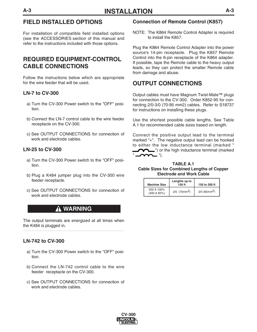
CV-300 specifications
The Lincoln Electric CV-300 is a highly regarded power source designed specifically for wire feed welding applications. This machine combines advanced technology with user-friendly features to meet the demanding needs of professional welders. Known for its reliability, efficiency, and versatility, the CV-300 is suitable for various welding processes, including MIG, flux-cored, and DC TIG welding.One of the standout features of the CV-300 is its constant voltage design. This ensures a stable arc throughout the welding process, which is critical for achieving high-quality welds. The ability to maintain a consistent arc helps in reducing spatter and improves bead appearance, making it ideal for both novice and experienced welders.
The CV-300 is equipped with Lincoln Electric's exclusive Auto-Set technology. This feature simplifies the setup process significantly by allowing users to select the material type and thickness. The machine automatically adjusts the voltage and wire feed speed, ensuring optimal performance without requiring extensive knowledge of welding parameters from the operator.
Another defining characteristic of the CV-300 is its robust construction. Built to endure the rigors of the shop environment, the power source features a durable housing and components that withstand high heat and heavy use. Additionally, it is designed for easy access to internal components, facilitating maintenance and servicing when required.
Portability is another significant advantage of the Lincoln Electric CV-300. Weighing in at a manageable size, the power source can easily be transported to job sites or moved around the workshop, enhancing its usability. It is compatible with various wire feeders, making it an adaptable choice for different welding projects, whether it's light fabrication or heavier industrial work.
The CV-300 also supports a variety of input voltages, making it versatile for use in different settings. Its adaptability allows it to operate efficiently in various environments, ensuring that welders have the power they need at their fingertips.
In summary, the Lincoln Electric CV-300 is a formidable choice for those in need of reliable and powerful welding equipment. With features such as constant voltage output, Auto-Set technology, robust construction, and portability, it meets the demands of modern welding with ease, helping professionals achieve stunning results in their work.

