MAINTENANCE
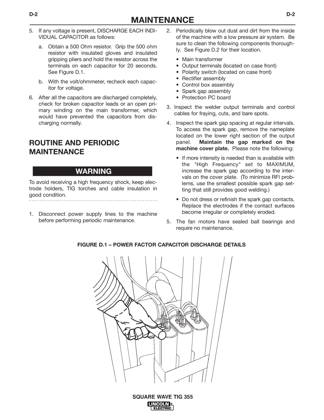
5.If any voltage is present, DISCHARGE EACH INDI- VIDUAL CAPACITOR as follows:
a.Obtain a 500 Ohm resistor. Grip the 500 ohm resistor with insulated gloves and insulated gripping pliers and hold the resistor across the terminals on each capacitor for 20 seconds. See Figure D.1.
b.With the volt/ohmmeter, recheck each capac- itor for voltage.
6.After all the capacitors are discharged completely, check for broken capacitor leads or an open pri- mary winding on the main transformer, which would have prevented the capacitors from dis- charging normally.
ROUTINE AND PERIODIC
MAINTENANCE
WARNING
To avoid receiving a high frequency shock, keep elec- trode holders, TIG torches and cable insulation in good condition.
1.Disconnect power supply lines to the machine before performing periodic maintenance.
2.Periodically blow out dust and dirt from the inside of the machine with a low pressure air system. Be sure to clean the following components thorough- ly. See Figure D.2 for their location.
•Main transformer
•Output terminals (located on case front)
•Polarity switch (located on case front)
•Rectifier assembly
•Control box assembly
•Spark gap assembly
•Protection PC board
3.Inspect the welder output terminals and control cables for fraying, cuts, and bare spots.
4.Inspect the spark gap spacing at regular intervals. To access the spark gap, remove the nameplate located on the lower right section of the output panel. Maintain the gap marked on the machine cover plate. Please note the following:
•If more intensity is needed than is available with the "High Frequency" set to MAXIMUM, increase the spark gap according to the inter- vals on the cover plate. (To minimize RFI prob- lems, use the smallest possible spark gap set- ting that still provides good welding.)
•Do not dress or refinish the spark gap contacts. Replace the electrodes if the contact surfaces become irregular or completely eroded.
5.The fan motors have sealed ball bearings and require no maintenance.
