OPERATION
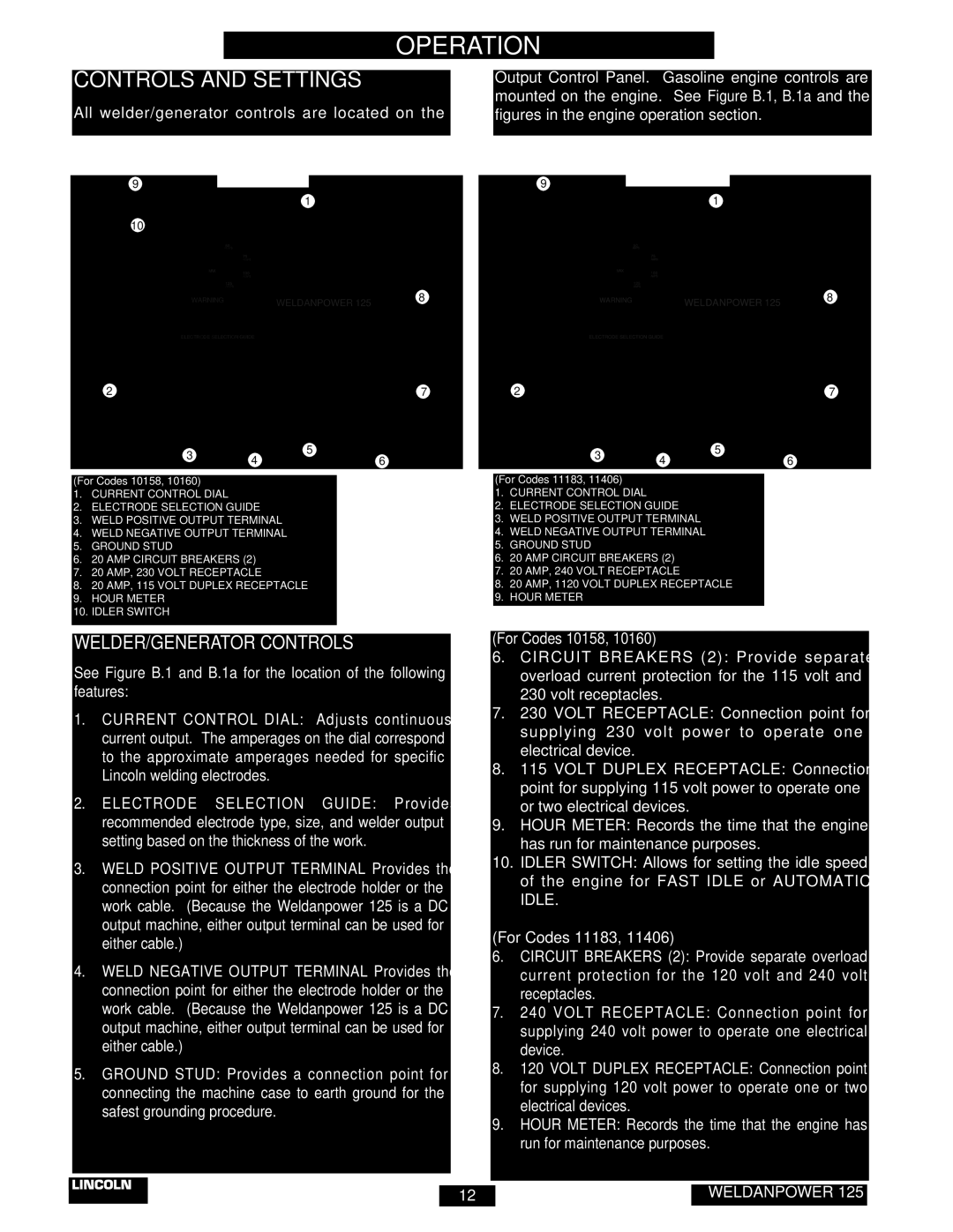
CONTROLS AND SETTINGS | Output Control Panel. Gasoline engine controls are |
All welder/generator controls are located on the | mounted on the engine. See Figure B.1, B.1a and the |
figures in the engine operation section. |
FIGURE B.1 and B.1a – OUTPUT PANEL CONTROLS
| 9 | FIGURE B.1 |
| |
|
|
|
| |
|
|
| 1 |
|
| 10 |
|
|
|
| HOURS | 50 |
|
|
|
|
|
| |
|
| AMPS |
|
|
|
| 75 |
|
|
|
| AMPS |
|
|
|
| MAX |
|
|
|
| 100 |
|
|
|
| AMPS |
|
|
| IDLER | 125 |
|
|
|
|
|
| |
|
| AMPS |
|
|
| WARNING | WELDANPOWER 125 | 8 | |
|
|
|
| |
| ELECTRODE SELECTION GUIDE |
|
| |
2 | + | - | 5 | 7 |
|
|
|
| |
| 3 | 4 | 5 | 6 |
|
| |||
|
|
| ||
(For Codes 10158, 10160)
1.CURRENT CONTROL DIAL
2.ELECTRODE SELECTION GUIDE
3.WELD POSITIVE OUTPUT TERMINAL
4.WELD NEGATIVE OUTPUT TERMINAL
5.GROUND STUD
6.20 AMP CIRCUIT BREAKERS (2)
7.20 AMP, 230 VOLT RECEPTACLE
8.20 AMP, 115 VOLT DUPLEX RECEPTACLE
9.HOUR METER
10.IDLER SWITCH
FIGURE B.1a
9
|
|
| 1 |
|
| HOURS | 50 |
|
|
|
|
|
| |
|
| AMPS |
|
|
|
| 75 |
|
|
|
| AMPS |
|
|
| MAX | 100 |
|
|
|
|
|
| |
|
| AMPS |
|
|
|
| 125 |
|
|
|
| AMPS |
|
|
| WARNING |
| WELDANPOWER 125 | 8 |
|
|
|
| |
| ELECTRODE SELECTION GUIDE |
|
| |
2 | + | - | 5 | 7 |
|
|
|
| |
| 3 | 4 | 5 | 6 |
|
| |||
|
|
| ||
(For Codes 11183, 11406)
1.CURRENT CONTROL DIAL
2.ELECTRODE SELECTION GUIDE
3.WELD POSITIVE OUTPUT TERMINAL
4.WELD NEGATIVE OUTPUT TERMINAL
5.GROUND STUD
6.20 AMP CIRCUIT BREAKERS (2)
7.20 AMP, 240 VOLT RECEPTACLE
8.20 AMP, 1120 VOLT DUPLEX RECEPTACLE
9.HOUR METER
WELDER/GENERATOR CONTROLS
See Figure B.1 and B.1a for the location of the following features:
1.CURRENT CONTROL DIAL: Adjusts continuous current output. The amperages on the dial correspond to the approximate amperages needed for specific Lincoln welding electrodes.
2.ELECTRODE SELECTION GUIDE: Provides recommended electrode type, size, and welder output setting based on the thickness of the work.
3.WELD POSITIVE OUTPUT TERMINAL Provides the connection point for either the electrode holder or the work cable. (Because the Weldanpower 125 is a DC output machine, either output terminal can be used for either cable.)
4.WELD NEGATIVE OUTPUT TERMINAL Provides the connection point for either the electrode holder or the work cable. (Because the Weldanpower 125 is a DC output machine, either output terminal can be used for either cable.)
5.GROUND STUD: Provides a connection point for connecting the machine case to earth ground for the safest grounding procedure.
(For Codes 10158, 10160)
6.CIRCUIT BREAKERS (2): Provide separate overload current protection for the 115 volt and 230 volt receptacles.
7.230 VOLT RECEPTACLE: Connection point for supplying 230 volt power to operate one electrical device.
8.115 VOLT DUPLEX RECEPTACLE: Connection point for supplying 115 volt power to operate one or two electrical devices.
9.HOUR METER: Records the time that the engine has run for maintenance purposes.
10.IDLER SWITCH: Allows for setting the idle speed of the engine for FAST IDLE or AUTOMATIC IDLE.
(For Codes 11183, 11406)
6.CIRCUIT BREAKERS (2): Provide separate overload current protection for the 120 volt and 240 volt receptacles.
7.240 VOLT RECEPTACLE: Connection point for supplying 240 volt power to operate one electrical device.
8.120 VOLT DUPLEX RECEPTACLE: Connection point for supplying 120 volt power to operate one or two electrical devices.
9.HOUR METER: Records the time that the engine has run for maintenance purposes.
– 12 – | WELDANPOWER 125 |