| MAINTENANCE | |
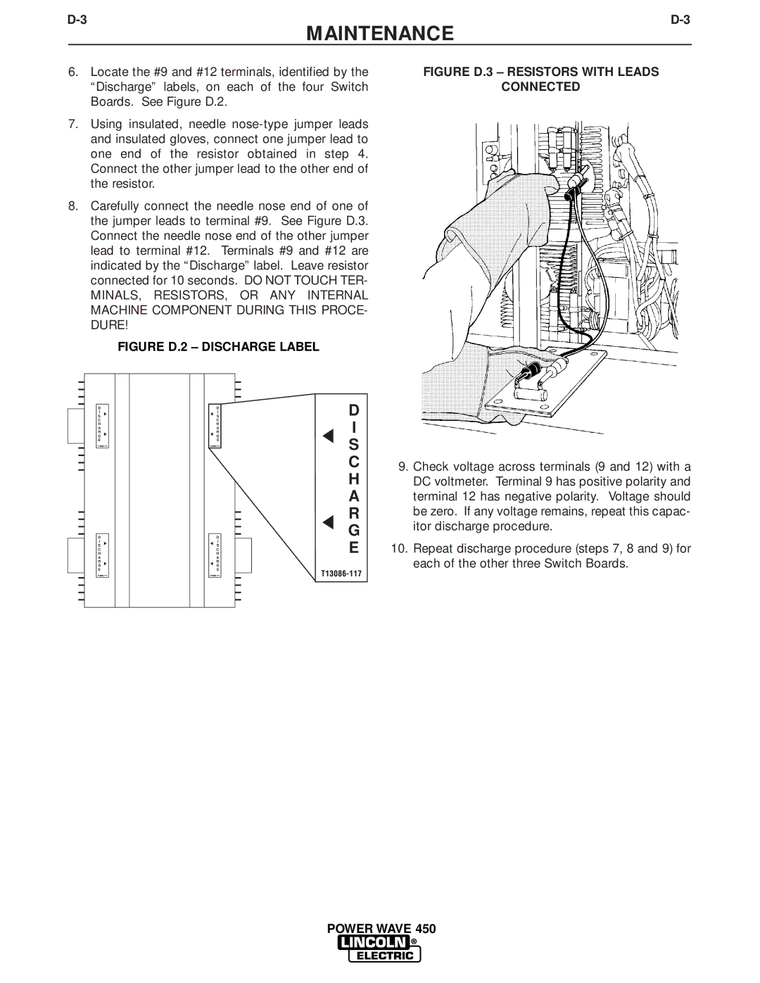
| 6. Locate the #9 and #12 terminals, identified by the | FIGURE D.3 – RESISTORS WITH LEADS |
| “Discharge” labels, on each of the four Switch | CONNECTED |
Boards. See Figure D.2.
7. Using insulated, needle
8. Carefully connect the needle nose end of one of the jumper leads to terminal #9. See Figure D.3. Connect the needle nose end of the other jumper lead to terminal #12. Terminals #9 and #12 are indicated by the “Discharge” label. Leave resistor connected for 10 seconds. DO NOT TOUCH TER-
MINALS, RESISTORS, OR ANY INTERNAL MACHINE COMPONENT DURING THIS PROCE- DURE!
FIGURE D.2 – DISCHARGE LABEL
D
I
S C H A R G E
D
I
S C H A R G E
D
I
S C H A R G E
D
I
S C H A R G E
D
I
S C H A R G E
9.Check voltage across terminals (9 and 12) with a DC voltmeter. Terminal 9 has positive polarity and terminal 12 has negative polarity. Voltage should be zero. If any voltage remains, repeat this capac- itor discharge procedure.
10.Repeat discharge procedure (steps 7, 8 and 9) for each of the other three Switch Boards.
POWER WAVE 450