VIVOTEK
DI/DO Diagram
Please refer to the following illustration for the connection method.
12V
PIN 1
Power+12V
PIN 2
Digital output
+12V
PIN 3
Digital input
PIN 4
Ground
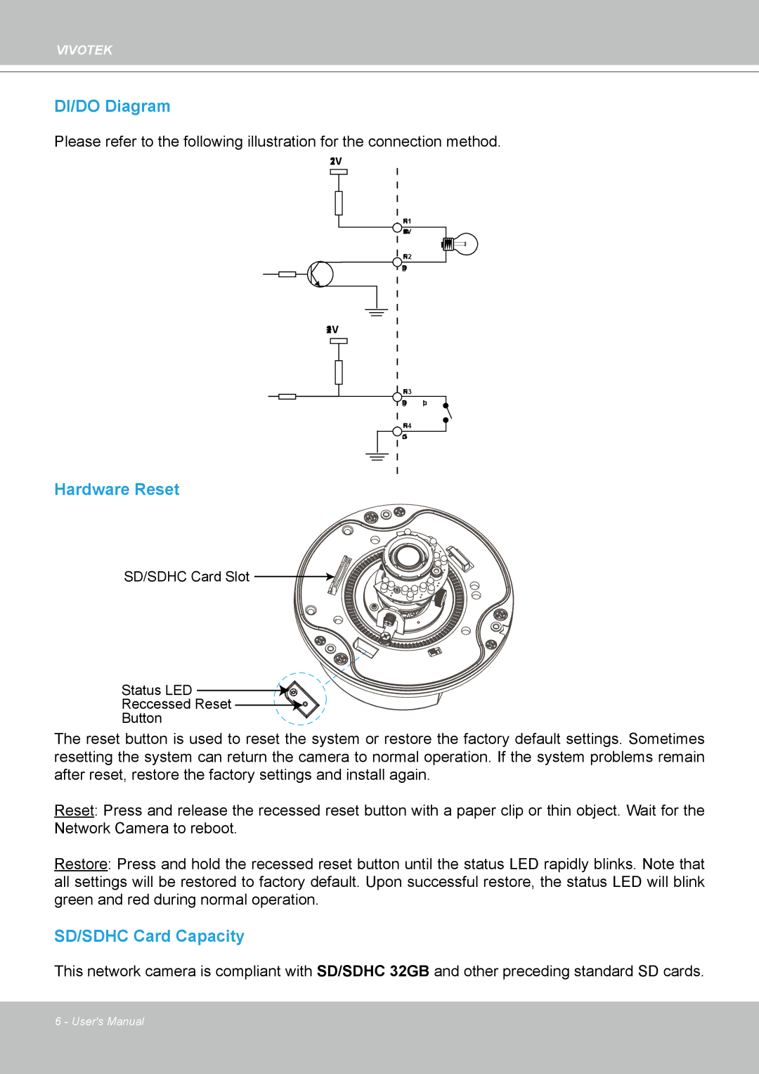
Hardware Reset
SD/SDHC Card Slot 

![]()
![]()
![]()
![]()
![]()
![]()
![]()
![]()
![]()
![]()
Status LED
Reccessed Reset ![]()
![]()
Button
The reset button is used to reset the system or restore the factory default settings. Sometimes resetting the system can return the camera to normal operation. If the system problems remain after reset, restore the factory settings and install again.
Reset: Press and release the recessed reset button with a paper clip or thin object. Wait for the Network Camera to reboot.
Restore: Press and hold the recessed reset button until the status LED rapidly blinks. Note that all settings will be restored to factory default. Upon successful restore, the status LED will blink green and red during normal operation.
SD/SDHC Card Capacity
This network camera is compliant with SD/SDHC 32GB and other preceding standard SD cards.
6 - User's Manual