INSTALLATION | ||
|
|
|
b)Push the end connector from torch into
c)Attach the water lines from the torch power cables to a supply of cooling water.
d)Connect the water lines from the nozzle bundle to the Tandem MIG interface. If a Tandem MIG interface is not used, connect the water lines directly to the water cooler or other type of con- troller.
e)For
Connect the shielding gas line from the nozzle bundle to the Tandem MIG interface. Alternatively, connect the shielding gas line to the lead wire feeder. Do not connect the shielding gas line to trail wire feeder, because there would be no shield- ing gas in the event of a delayed trail arc start .
For
Shielding gas connection was completed in step b, when torch cables were connected to
f)Attach the air blast line to the high pressure dry air supply
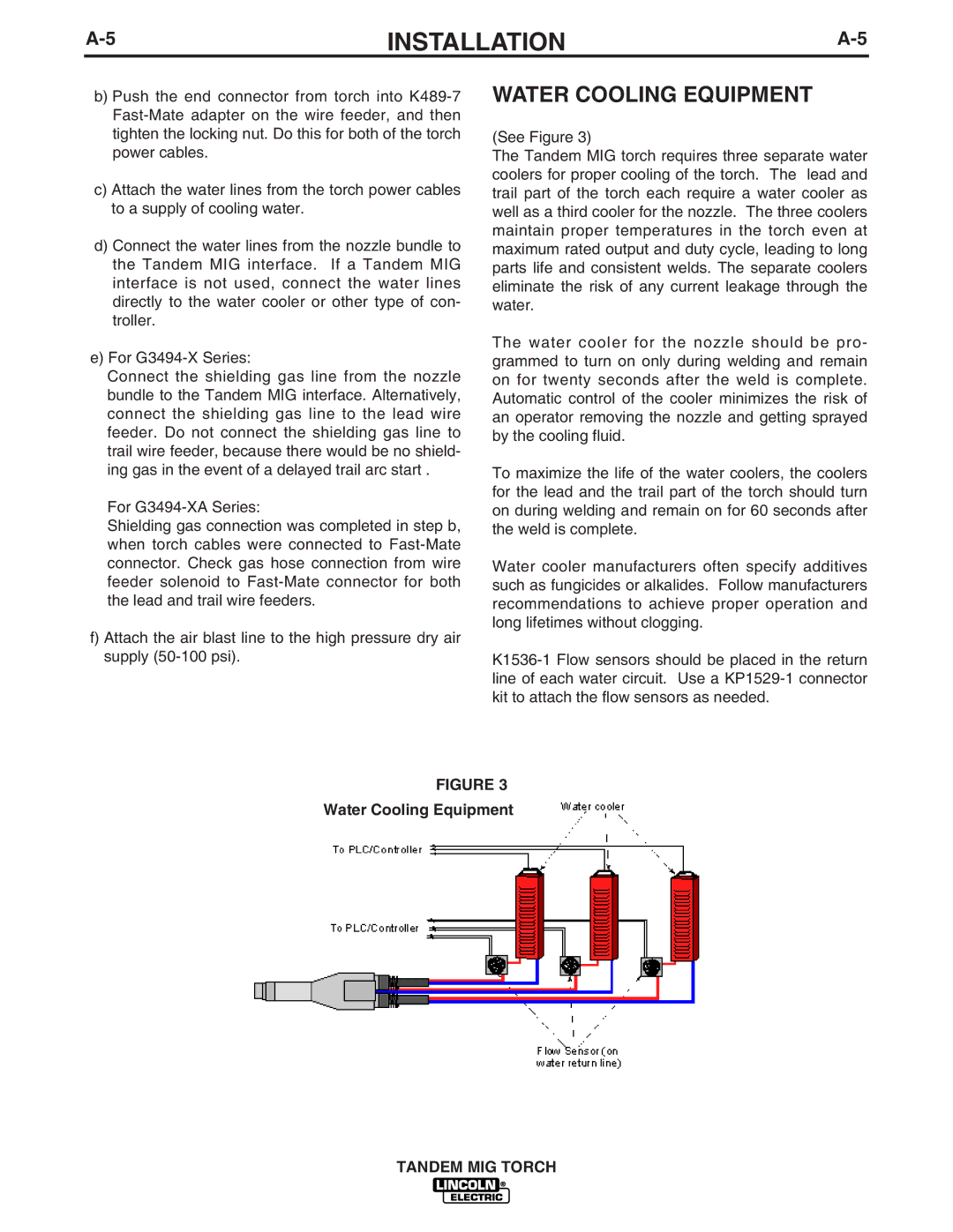
WATER COOLING EQUIPMENT
(See Figure 3)
The Tandem MIG torch requires three separate water coolers for proper cooling of the torch. The lead and trail part of the torch each require a water cooler as well as a third cooler for the nozzle. The three coolers maintain proper temperatures in the torch even at maximum rated output and duty cycle, leading to long parts life and consistent welds. The separate coolers eliminate the risk of any current leakage through the water.
The water cooler for the nozzle should be pro- grammed to turn on only during welding and remain on for twenty seconds after the weld is complete. Automatic control of the cooler minimizes the risk of an operator removing the nozzle and getting sprayed by the cooling fluid.
To maximize the life of the water coolers, the coolers for the lead and the trail part of the torch should turn on during welding and remain on for 60 seconds after the weld is complete.
Water cooler manufacturers often specify additives such as fungicides or alkalides. Follow manufacturers recommendations to achieve proper operation and long lifetimes without clogging.
FIGURE 3 Water Cooling Equipment
TANDEM MIG TORCH