| INSTALLATION |
| ||
|
|
|
|
|
PARALLEL OPERATION
The
To set machine outputs, start with output control pots and arc control pots in identical positions. Use the output control pots to balance the currents and main- tain the desired voltage or current. The arc control pots should be kept identical on the two machines.
QUICK DISCONNECT PLUGS
A quick disconnect system is used for the welding cable connections. The welding plug included with the machine is designed to accept a welding cable size of 1/0 to 2/0.
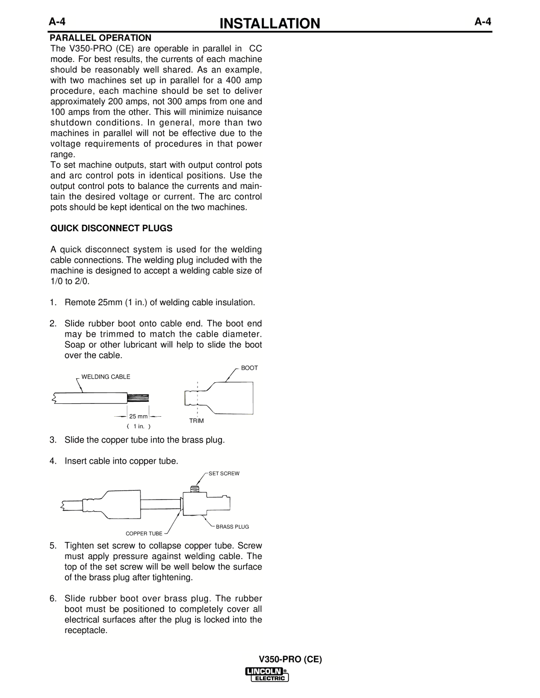
1.Remote 25mm (1 in.) of welding cable insulation.
2.Slide rubber boot onto cable end. The boot end may be trimmed to match the cable diameter. Soap or other lubricant will help to slide the boot over the cable.
WELDING CABLE
![]() 25 mm
25 mm![]()
BOOT
TRIM
1in.
3.Slide the copper tube into the brass plug.
4.Insert cable into copper tube.
SET SCREW
BRASS PLUG
COPPER TUBE
5.Tighten set screw to collapse copper tube. Screw must apply pressure against welding cable. The top of the set screw will be well below the surface of the brass plug after tightening.
6.Slide rubber boot over brass plug. The rubber boot must be positioned to completely cover all electrical surfaces after the plug is locked into the receptacle.