INSTALLATION | ||
|
|
|
SAFETY PRECAUTIONS
![]() WARNING
WARNING
ELECTRIC SHOCK can kill.
•TURN THE INPUT POWER OFF AT THE DISCONNECT SWITCH BEFORE ATTEMPTING TO CONNECT OR DIS- CONNECT INPUT POWER LINES,
OUTPUT CABLES, OR CONTROL CABLES.
•Only qualified personnel should perform this installation.
•Connect the green/yellow lead of the power cord to ground per U.S.National Electrical Code.
SELECT SUITABLE LOCATION
The Invertec POWER WAVE 405 will operate in harsh environments. Even so, it is important that simple pre- ventative measures are followed in order to assure long life and reliable operation.
•The machine must be located where there is free cir- culation of clean air such that air movement in the back, out the sides and bottom will not be restricted.
•Dirt and dust that can be drawn into the machine should be kept to a minimum. Failure to observe these precautions can result in excessive operating temperatures and nuisance shutdown.
•Keep machine dry. Shelter from rain and snow. Do not place on wet ground or in puddles.
•DO NOT MOUNT OVER COMBUSTIBLE SURFACES.
![]() CAUTION
CAUTION
Where there is a combustible surface directly under stationary or fixed electrical equipment, that surface shall be covered with a steel plate at least .06”(1.6mm) thick, which shall extend not less than 5.90”(150mm) beyond the equipment on all sides.
STACKING
POWER WAVE 405 cannot be stacked.
TILTING
Place the machine directly on a secure, level surface or on a recommended undercarriage. The machine may topple over if this procedure is not followed.
INPUT AND GROUNDING CONNECTIONS
•Only a qualified electrician should connect the Invertec POWER WAVE 405. Installation should be made in accordance with the appropriate National Electrical Code, all local codes and the information detailed below.
•When received directly from the factory, multiple voltage machines are internally connected for 400VAC. If 400VAC is the desired input, then the machine may be connected to the power system without any setup required inside the machine.
•Initial 200VAC - 230VAC operation will require an Input voltage panel setup.
•Open the access panel on the rear of the machine.
•For 200 or 230: Position the large switch to 200- 230.
For higher voltages: Position the large switch to greater than 380.
•Move the "A" lead to the appropriate terminal.
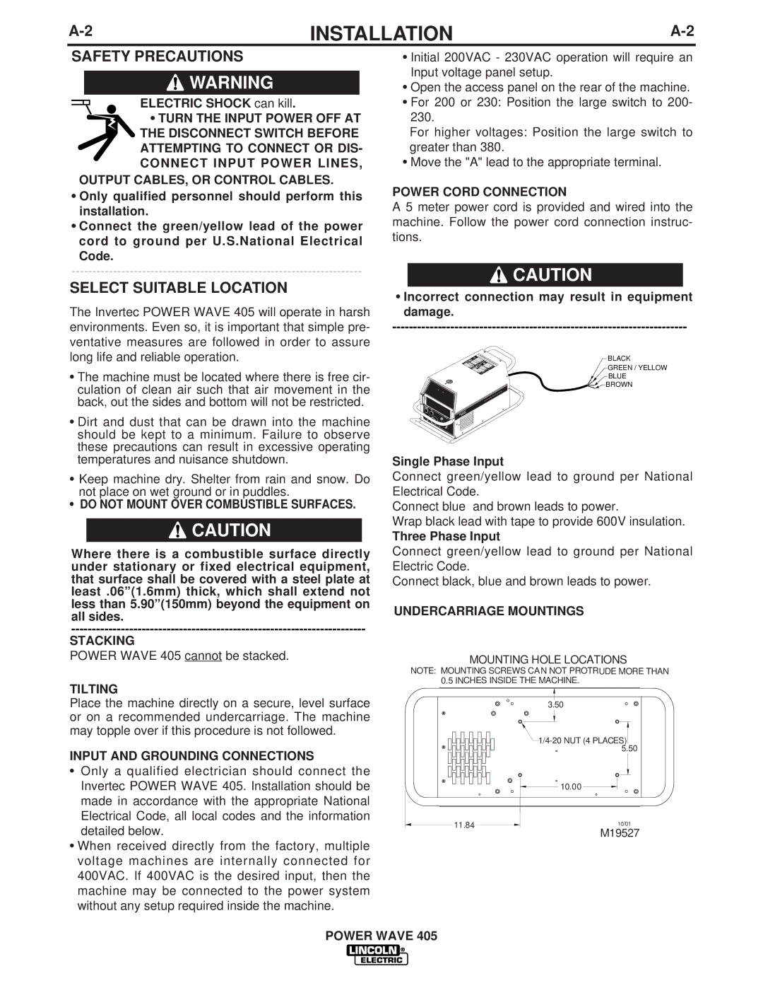
POWER CORD CONNECTION
A 5 meter power cord is provided and wired into the machine. Follow the power cord connection instruc- tions.
![]() CAUTION
CAUTION
•Incorrect connection may result in equipment damage.
BLACK
GREEN / YELLOW
BLUE
![]()
![]() BROWN
BROWN
Single Phase Input
Connect green/yellow lead to ground per National Electrical Code.
Connect blue and brown leads to power.
Wrap black lead with tape to provide 600V insulation.
Three Phase Input
Connect green/yellow lead to ground per National Electric Code.
Connect black, blue and brown leads to power.
UNDERCARRIAGE MOUNTINGS
MOUNTING HOLE LOCATIONS
NOTE: MOUNTING SCREWS CAN NOT PROTRUDE MORE THAN 0.5 INCHES INSIDE THE MACHINE.
3.50 |
![]() 1/4-20
1/4-20
10.00
11.84 |
| 10/01 |
|
M19527