INSTALLATION | ||
|
|
|
I / O RECEPTACLE SPECIFICATIONS
TABLE A.2
WIRE FEEDER RECEPTACLE
PIN LEAD# | FUNCTION |
A53 Communication Bus L
B54 Communication Bus H
C67A Electrode Voltage Sense
D | 52 | 0vdc |
E | 51 | +40vdc |
TABLE A.3
VOLTAGE SENSE RECEPTACLE
| PIN | LEAD# | FUNCTION |
| 3 | 21A | Work Voltage Sense |
|
| TABLE A.4 | |
|
| RS232 RECEPTACLE | |
| PIN | LEAD# | FUNCTION |
2253 RS232 Receive
3254 RS232 Transmit
4 | # | Pin5 |
5 | # | Pin4 |
6 | # # | Pin20 |
20 | # # | Pin6 |
7 | 251 | RS232 Commom |
DIP SWITCH SETTINGS AND LOCATIONS
DIP switches on the P.C. Boards allow for custom configuration of the Power Wave. To access the DIP switches:
![]() WARNING
WARNING
ELECTRIC SHOCK can kill.
1.Turn off power to the power source at the disconnect switch.
2.Remove the wrap around cover from the power source.
3.The control board is on the center assembly facing the case front. Locate the
4.Using a pencil or other small object, slide the switch to the OFF position if the work sense lead is NOT connected. Conversely, slide the switch to the ON position if the work sense lead is present.
O
N
1 2 3 4 5 6 7 8
CONTROL BOARD DIP SWITCH:
switch 1 = reserved for future use switch 2 = reserved for future use switch 3 = reserved for future use switch 4 = reserved for future use switch 5 = reserved for future use switch 6 = reserved for future use switch 7 = reserved for future use switch 8* = work sense lead
switch 8* | work sense lead |
off | work sense lead not connected |
on | work sense lead connected |
|
|
*Factory setting for Switch 8 is OFF.
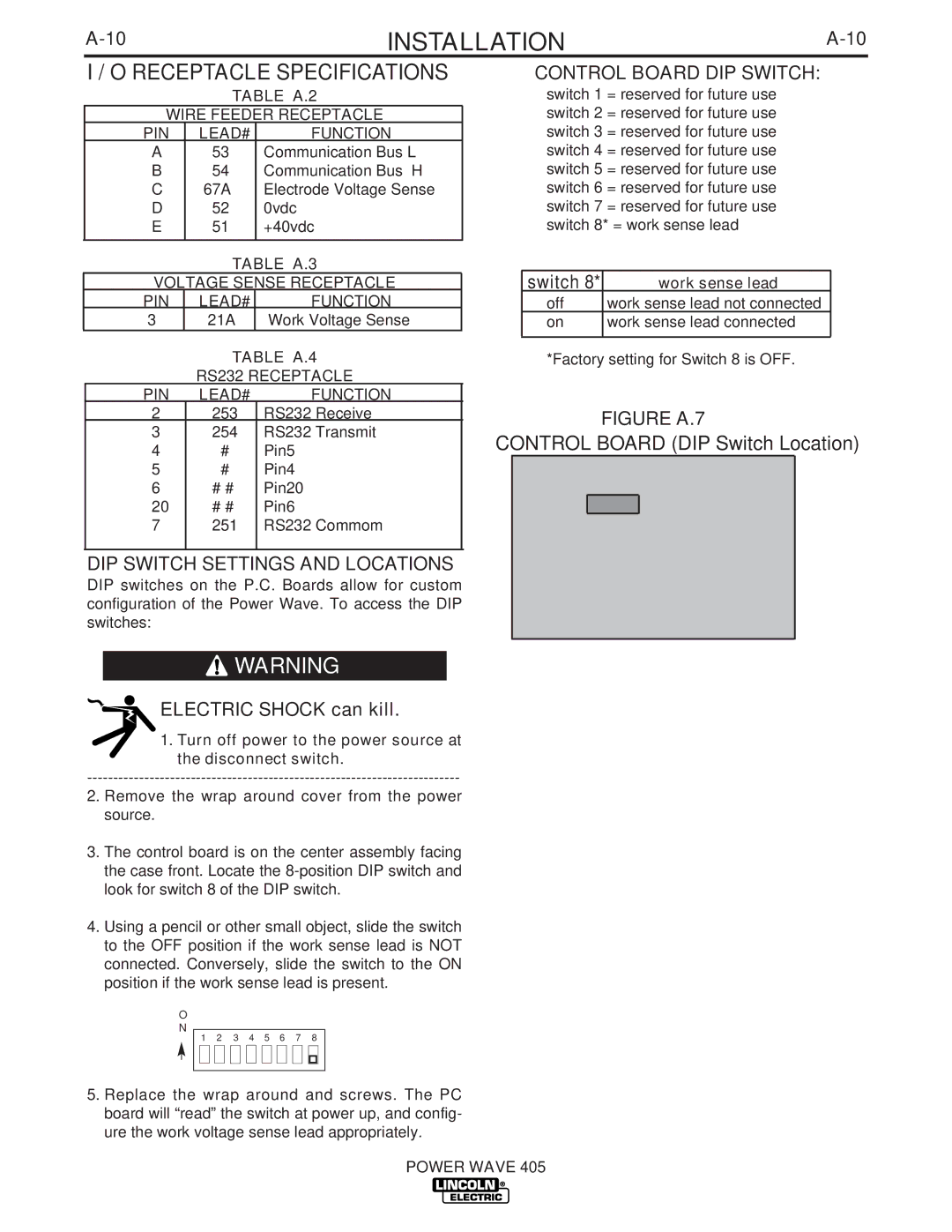
FIGURE A.7
CONTROL BOARD (DIP Switch Location)
5.Replace the wrap around and screws. The PC board will “read” the switch at power up, and config- ure the work voltage sense lead appropriately.