MAINTENANCE |
COMPONENT REPLACEMENT PROCEDURES
CHANGING THE CONTACT TIP
1.Unplug or turn power switch to Off “O” position.
2.Refer to Figure D.2. Remove the gas nozzle from the gun by unscrewing
3.Remove the existing contact tip from the gun by unscrewing
4.Insert and hand tighten desired contact tip.
5.Replace gas nozzle.
CHANGING THE
•Change The Contact Tip
•Acquire Innershield Welding Kit (See ACCES- SORIES section). Note: Feeding .035” Innershield requires nothing extra but feeding will be optimized with the use of the
1.Refer to Figure D.2. Remove the gas nozzle from the gun by unscrewing
CAUTION
When inching the welding wire, the drive rolls, gun connector block, and gun contact tip are energized relative to work and ground and remain energized for several seconds after the gun trig- ger is released.
4.Remove the drive roll, flip over and reinstall with the opposite groove closest to the gearbox.
NOTE: The stencil of the groove that you want to use is marked on the outside of the drive roll (when installed)
5.Push a length of straightened welding wire through the wire feeder guide tubes and reset the Phillips Head screw to secure the drive roll onto the shaft.
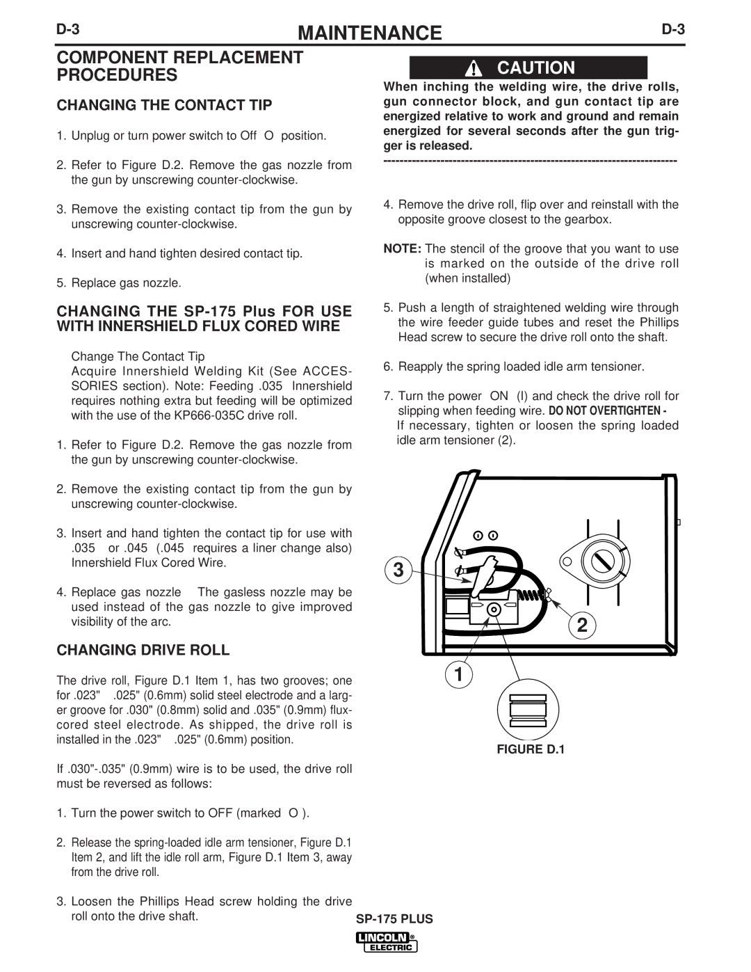
6.Reapply the spring loaded idle arm tensioner.
7.Turn the power “ON” (I) and check the drive roll for slipping when feeding wire. DO NOT OVERTIGHTEN - If necessary, tighten or loosen the spring loaded idle arm tensioner (2).
2.Remove the existing contact tip from the gun by unscrewing
3.Insert and hand tighten the contact tip for use with
.035” or .045” (.045” requires a liner change also) Innershield Flux Cored Wire.
4.Replace gas nozzle – The gasless nozzle may be used instead of the gas nozzle to give improved visibility of the arc.
CHANGING DRIVE ROLL
3 ![]()
![]()
![]()
2
The drive roll, Figure D.1 Item 1, has two grooves; one | 1 |
for .023"
FIGURE D.1
1.Turn the power switch to OFF (marked “O”).
2.Release the
3.Loosen the Phillips Head screw holding the drive
roll onto the drive shaft. |
|