INSTALLATION |
Read entire installation section before starting installation.
SAFETY PRECAUTIONS
![]() WARNING
WARNING
ELECTRIC SHOCK can kill.
•Only qualified personnel should perform this installation.
•Only personnel that have read and under- stood the
•Machine must be plugged into a receptacle which is grounded per any national, local or other applicable electrical codes.
• The
IDENTIFY AND LOCATE
COMPONENTS
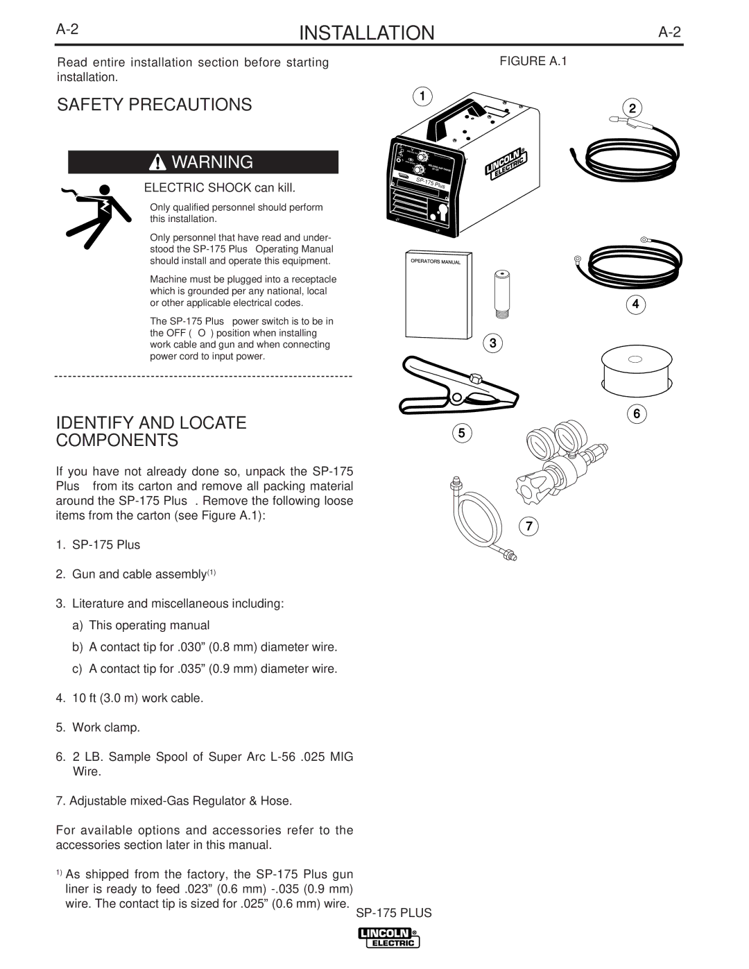
FIGURE A.1
1
2
WEL |
|
|
|
DING | AMP R |
| |
25- |
| ANGE | |
| 125 | ||
SP- |
|
|
|
175 | Plus | ||
| |||
4
3
6
5
If you have not already done so, unpack the
7
1.
2.Gun and cable assembly(1)
3.Literature and miscellaneous including:
a)This operating manual
b)A contact tip for .030” (0.8 mm) diameter wire.
c)A contact tip for .035” (0.9 mm) diameter wire.
4.10 ft (3.0 m) work cable.
5.Work clamp.
6.2 LB. Sample Spool of Super Arc
7.Adjustable
For available options and accessories refer to the accessories section later in this manual.
1)As shipped from the factory, the