OPERATION | ||
|
|
|
When in the TOUCH START TIG mode and when a Amptrol is connected to the
The ARC CONTROL is not active in the TIG mode.
The RANGER 305D (CE) can be used in a wide variety of DC TIG welding applications. In general the ‘Touch Start’ feature allows contamination free starting without the use of a
RANGER 305D (CE) settings when using the
•Set the MODE Switch to the TOUCH START TIG setting.
•Set the "IDLER" Switch to the "AUTO" position.
•Set the "WELDING TERMINALS" switch to the "REMOTELY CONTROLLED" position. This will keep the "Solid State" contactor open and provide a “cold” electrode until the Amptrol or Arc Start Switch is pressed
When using the TIG Module, the OUTPUT control on the RANGER 305D (CE) is used to set the maximum range of the CURRENT CONTROL on the TIG module or an Amptrol if connected to the TIG Module. (See Table B.2.)
WIRE WELDING-CV
Connect a wire feeder to the Ranger 305D according to the instructions in INSTALLATION INSTRUCTIONS Section.
The RANGER 305D (CE) in the
For any electrodes the procedures should be kept within the rating of the machine. For additional elec- trode information see WWW.Lincolnelectric.com or the appropriate Lincoln publication.
ARC GOUGING
The RANGER 305D (CE) can be used for limited arc gouging. For optimal performance, set the MODE switch to
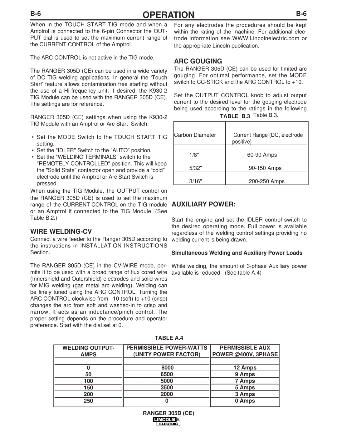
Set the OUTPUT CONTROL knob to adjust output current to the desired level for the gouging electrode being used according to the ratings in the following
Table B.3.
Carbon Diameter | Current Range (DC, electrode |
|
| positive) |
|
1/8" |
| |
5/32" |
| |
3/16" |
|
AUXILIARY POWER:
Start the engine and set the IDLER control switch to the desired operating mode. Full power is available regardless of the welding control settings providing no welding current is being drawn.
Simultaneous Welding and Auxiliary Power Loads
While welding, the amount of
|
|
|
| TABLE A.4 |
|
|
| |
|
|
|
|
|
|
|
|
|
| WELDING OUTPUT- |
|
| PERMISSIBLE |
| PERMISSIBLE AUX | ||
| AMPS |
|
| (UNITY POWER FACTOR) |
| POWER @400V, 3PHASE | ||
|
|
|
|
|
|
|
|
|
| 0 |
|
| 8000 |
| 12 Amps | ||
| 50 |
|
| 6500 |
|
| 9 Amps |
|
| 100 |
|
| 5000 |
|
| 7 Amps |
|
| 150 |
|
| 3500 |
|
| 5 Amps |
|
| 200 |
|
| 2000 |
|
| 3 Amps |
|
| 250 |
|
| 0 |
|
| 0 Amps |
|
|
|
|
|
|
|
|
|
|