OPERATION | ||
|
|
|
WELDER OPERATION
DUTY CYCLE
Duty Cycle is the percentage of time the load is being applied in a 10 minute period. For example a 60% duty cycle, represents 6 minutes of load and 4 minutes of no load in a 10 minute period.
The RANGER 305D (CE) can be used with a broad range of DC stick electrodes. The MODE switch provides two stick welding settings as follows:
CONSTANT CURRENT (CC-STICK) Welding
The
The OUTPUT CONTROL dial adjusts the full output range for stick welding.
The ARC CONTROL dial sets the short circuit current (arc- force) during stick welding to adjust for a soft or crisp arc. Increasing the dial from
DOWNHILL PIPE (STICK) Welding
The DOWNHILL PIPE position of the MODE switch is a slope controlled setting intended for
The OUTPUT CONTROL dial adjusts the full output range for stick welding. The ARC CONTROL dial sets the short circuit current
TIG WELDING
The TOUCH START TIG setting of the MODE switch is for DC TIG (Tungsten Inert Gas) welding. To initiate a weld, the OUTPUT CONTROL dial is first set to the desired cur- rent and the tungsten is touched to the work. During the time the tungsten is touching the work there is very little voltage or current and, in general, no tungsten contamina- tion. Then, the tungsten is gently lifted off the work in a rocking motion, which establishes the arc.
To stop the arc, simply lift the TIG torch away from the work piece. When the arc voltage reaches approximately 30 volts, the arc will go out and the machine will automati- cally reset to the touch start current level. The tungsten may then be retouched to the work piece to restrike the arc. The arc may also be started and stopped with an Amptrol or Arc Start Switch. See the following para- graphs.
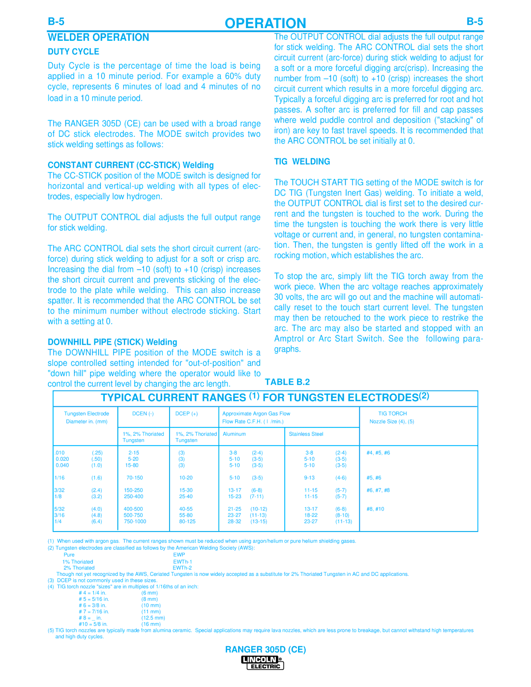
TABLE B.2
TYPICAL CURRENT RANGES (1) FOR TUNGSTEN ELECTRODES(2)
Tungsten Electrode | DCEN | DCEP (+) | Approximate Argon Gas Flow |
| TIG TORCH |
| ||||
Diameter in. (mm) |
|
| Flow Rate C.F.H. ( l | /min.) |
| Nozzle Size (4), (5) | ||||
|
|
|
|
|
|
|
|
|
|
|
|
| 1%, 2% Thoriated | 1%, 2% Thoriated | Aluminum |
|
| Stainless Steel |
|
|
|
|
| Tungsten | Tungsten |
|
|
|
|
|
|
|
|
|
|
|
|
|
|
|
|
|
|
.010 | (.25) | (3) |
| #4, #5, #6 |
| |||||
0.020 | (.50) | (3) |
|
|
| |||||
0.040 | (1.0) | (3) |
|
|
| |||||
1/16 | (1.6) |
| #5, #6 |
| ||||||
3/32 | (2.4) |
| #6, #7, #8 |
| ||||||
1/8 | (3.2) |
|
|
| ||||||
5/32 | (4.0) |
| #8, #10 |
| ||||||
3/16 | (4.8) |
|
|
| ||||||
1/4 | (6.4) |
|
|
| ||||||
|
|
|
|
|
|
|
|
|
|
|
|
|
|
|
|
|
|
|
|
|
|
(1)When used with argon gas. The current ranges shown must be reduced when using argon/helium or pure helium shielding gases.
(2)Tungsten electrodes are classified as follows by the American Welding Society (AWS):
Pure | EWP |
1% Thoriated | |
2% Thoriated |
Though not yet recognized by the AWS, Ceriated Tungsten is now widely accepted as a substitute for 2% Thoriated Tungsten in AC and DC applications.
(3)DCEP is not commonly used in these sizes.
(4)TIG torch nozzle "sizes" are in multiples of 1/16ths of an inch:
# 4 = 1/4 in. | (6 mm) | |
# 5 | = 5/16 in. | (8 mm) |
# 6 | = 3/8 in. | (10 mm) |
# 7 | = 7/16 in. | (11 mm) |
# 8 | = _ in. | (12.5 mm) |
#10 = 5/8 in. | (16 mm) | |
(5)TIG torch nozzles are typically made from alumina ceramic. Special applications may require lava nozzles, which are less prone to breakage, but cannot withstand high temperatures and high duty cycles.