INSTALLATION | ||
|
|
|
OUTPUT CABLES, CONNECTIONS AND LIMITATIONS
Connect a work lead of sufficient size and length (per table A.1) between the proper output terminal on the power source and the work. Be sure the connection to the work makes tight
When using an inverter type power source like the Power Waves, use the largest welding (electrode and work) cables that are practical. At least 2/0 copper wire - even if the average output current would not normally require it. When pulsing, the pulse current can reach very high levels. Voltage drops can become excessive, leading to poor welding characteristics, if undersized welding cables are used.
CABLE INDUCTANCE, AND ITS EFFECTS ON PULSE WELDING
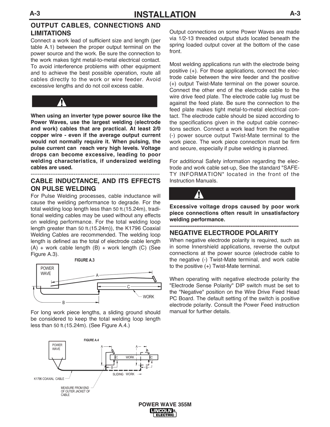
For Pulse Welding processes, cable inductance will cause the welding performance to degrade. For the total welding loop length less than 50 ft.(15.24m), tradi- tional welding cables may be used without any effects on welding performance. For the total welding loop length greater than 50 ft.(15.24m)), the K1796 Coaxial Welding Cables are recommended. The welding loop length is defined as the total of electrode cable length
(A) + work cable length (B) + work length (C) (See Figure A.3).
| FIGURE A.3 |
POWER |
|
WAVE | A |
|
C |
WORK |
B
For long work piece lengths, a sliding ground should be considered to keep the total welding loop length less than 50 ft.(15.24m). (See Figure A.4.)
| FIGURE A.4 |
|
|
POWER | A |
| A |
WAVE |
| ||
|
|
| |
| C | WORK | C |
![]()
![]() B
B ![]()
![]()
![]() B
B
SLIDING WORK
K1796 COAXIAL CABLE
MEASURE FROM END
OF OUTER JACKET OF
CABLE
Output connections on some Power Waves are made via
Most welding applications run with the electrode being positive (+). For those applications, connect the elec- trode cable between the wire feeder and the positive
(+)output
For additional Safety information regarding the elec- trode and work cable
Excessive voltage drops caused by poor work piece connections often result in unsatisfactory welding performance.
NEGATIVE ELECTRODE POLARITY
When negative electrode polarity is required, such as in some Innershield applications, reverse the output connections at the power source (electrode cable to the negative
When operating with negative electrode polarity the "Electrode Sense Polarity" DIP switch must be set to the "Negative" position on the Wire Drive Feed Head PC Board. The default setting of the switch is positive electrode polarity. Consult the Power Feed instruction manual for further details.
POWER WAVE 355M