INSTALLATION | ||
|
|
|
VOLTAGE SENSING
The best arc performance occurs when the Power Waves have accurate data about the arc conditions. Depending upon the process, inductance within the electrode and work lead cables can influence the apparent voltage at the studs of the welder. Voltage sense leads improve the accuracy of the arc condi- tions and can have a dramatic effect on performance. Sense Lead Kits
If the voltage sensing is enabled but the sense leads are missing, improperly connected, or if the electrode polarity switch is improperly configured, extremely high welding outputs may occur.
The ELECTRODE sense lead (67) is built into the control cable, and is automatically enabled for all
(21)connects to the Power Wave at the four pin con- nector. By default the WORK voltage is monitored at the output stud in the POWER WAVE 355M. For more information on the WORK sense lead (21), see "Work Voltage Sensing” in the following paragraph.
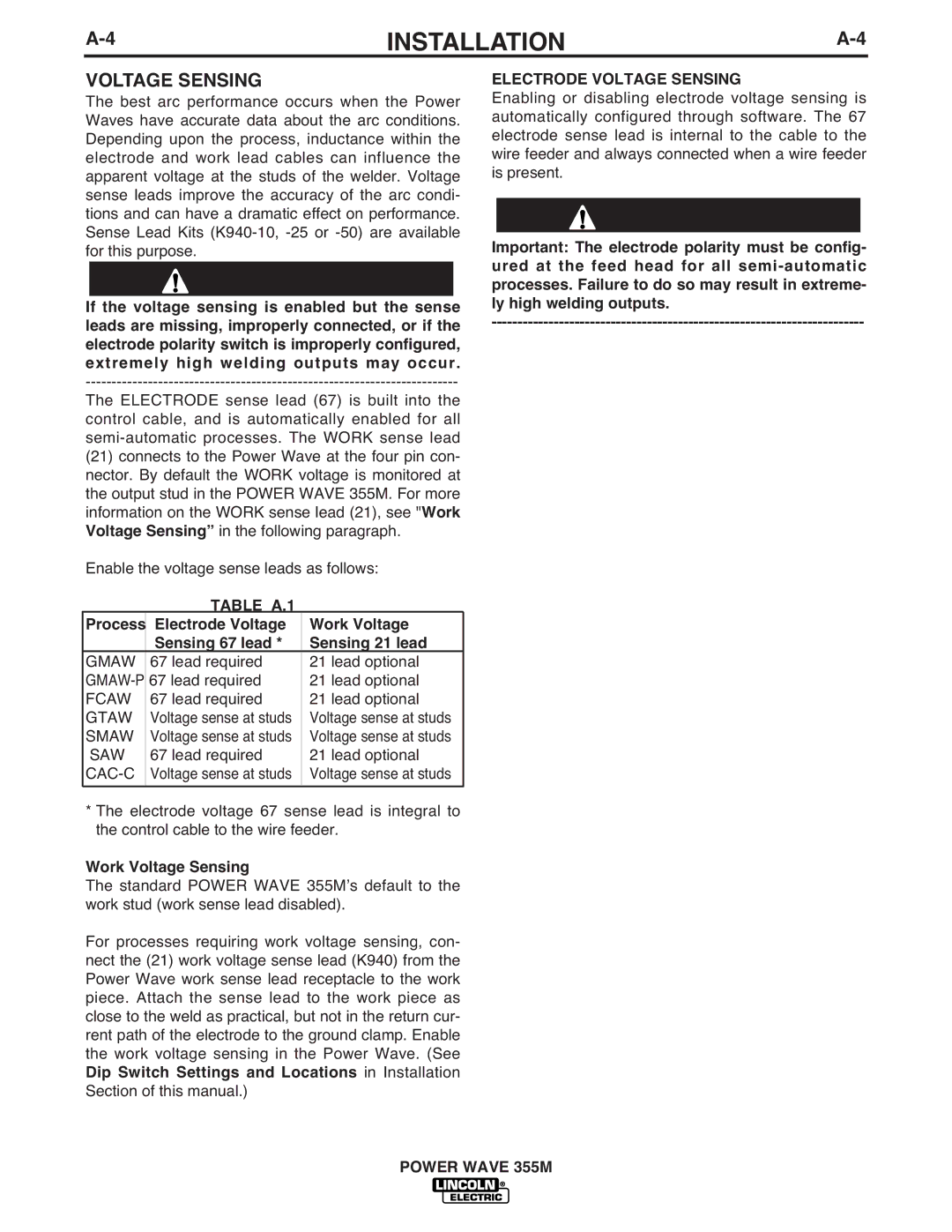
Enable the voltage sense leads as follows:
TABLE A.1
Process | Electrode Voltage | Work Voltage |
| Sensing 67 lead * | Sensing 21 lead |
GMAW | 67 lead required | 21 lead optional |
67 lead required | 21 lead optional | |
FCAW | 67 lead required | 21 lead optional |
GTAW | Voltage sense at studs | Voltage sense at studs |
SMAW | Voltage sense at studs | Voltage sense at studs |
SAW | 67 lead required | 21 lead optional |
| Voltage sense at studs | Voltage sense at studs |
|
|
|
*The electrode voltage 67 sense lead is integral to the control cable to the wire feeder.
Work Voltage Sensing
The standard POWER WAVE 355Mʼs default to the work stud (work sense lead disabled).
For processes requiring work voltage sensing, con- nect the (21) work voltage sense lead (K940) from the Power Wave work sense lead receptacle to the work piece. Attach the sense lead to the work piece as close to the weld as practical, but not in the return cur- rent path of the electrode to the ground clamp. Enable the work voltage sensing in the Power Wave. (See Dip Switch Settings and Locations in Installation Section of this manual.)
ELECTRODE VOLTAGE SENSING
Enabling or disabling electrode voltage sensing is automatically configured through software. The 67 electrode sense lead is internal to the cable to the wire feeder and always connected when a wire feeder is present.
Important: The electrode polarity must be config- ured at the feed head for all
POWER WAVE 355M
