INSTALLATION | ||
|
|
|
CONFIGURING THE SYSTEM
The power source will “Auto Map” the system eliminat- ing most of the need to set DIP switches to configure the system.
If a system can not be “Auto Mapped” then the status light on the power source will blink green fast and the welder output will be disabled.
If a system is not
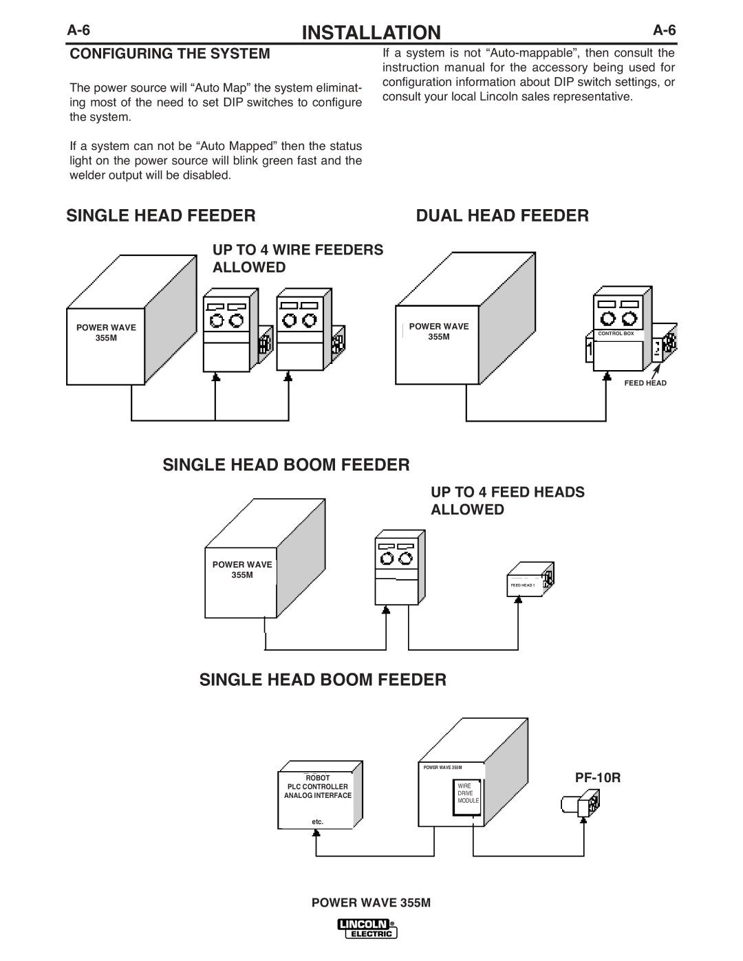
SINGLE HEAD FEEDER | DUAL HEAD FEEDER |
UP TO 4 WIRE FEEDERS
ALLOWED
POWER WAVE |
| POWER WAVE |
355M |
| 355M |
|
|
|
CONTROL BOX
FEED HEAD
SINGLE HEAD BOOM FEEDER
UP TO 4 FEED HEADS
ALLOWED
POWER WAVE
355M
FEED HEAD 1
SINGLE HEAD BOOM FEEDER
| POWER WAVE 355M | ||
ROBOT |
|
|
|
|
|
| |
PLC CONTROLLER |
| WIRE |
|
ANALOG INTERFACE |
| DRIVE |
|
|
| MODULE |
|
|
|
|
|
etc.
POWER WAVE 355M