MAINTENANCE | ||
|
|
|
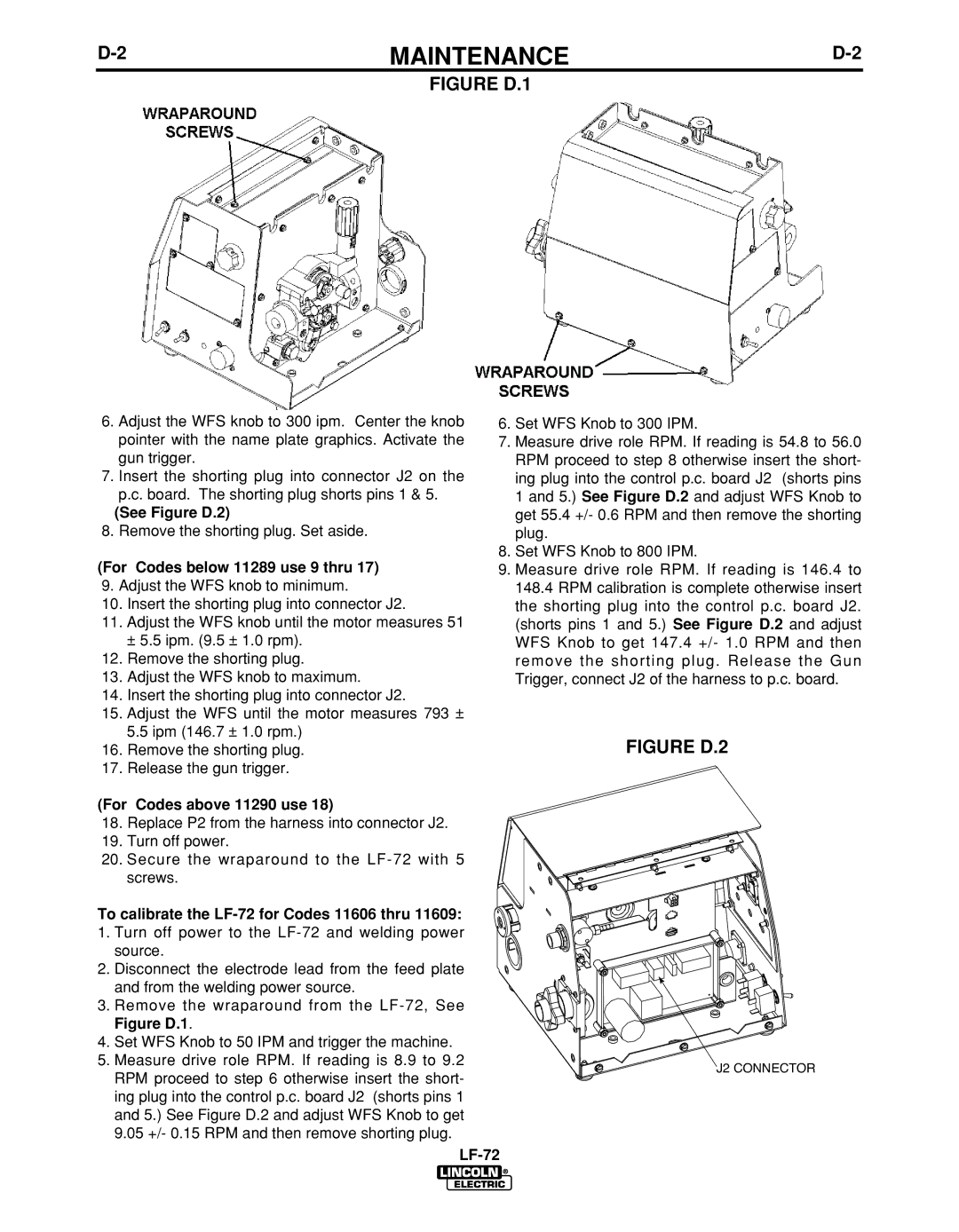
| FIGURE D.1 |
|
6. | Adjust the WFS knob to 300 ipm. Center the knob | 6. Set WFS Knob to 300 IPM. | |
| pointer with the name plate graphics. Activate the | 7. Measure drive role RPM. If reading is 54.8 to 56.0 | |
| gun trigger. | RPM proceed to step 8 otherwise insert the short- | |
7. | Insert the shorting plug into connector J2 on the | ing plug into the control p.c. board J2 (shorts pins | |
| p.c. board. The shorting plug shorts pins 1 & 5. | 1 and 5.) See Figure D.2 and adjust WFS Knob to | |
| (See Figure D.2) | get 55.4 +/- 0.6 RPM and then remove the shorting | |
8. | Remove the shorting plug. Set aside. | plug. | |
(For Codes below 11289 use 9 thru 17) | 8. Set WFS Knob to 800 IPM. | ||
9. Measure drive role RPM. If reading is 146.4 to | |||
9. | Adjust the WFS knob to minimum. | 148.4 RPM calibration is complete otherwise insert | |
10. | Insert the shorting plug into connector J2. | the shorting plug into the control p.c. board J2. | |
11. | Adjust the WFS knob until the motor measures 51 | (shorts pins 1 and 5.) See Figure D.2 and adjust | |
|
| ± 5.5 ipm. (9.5 ± 1.0 rpm). | WFS Knob to get 147.4 +/- 1.0 RPM and then |
12. | Remove the shorting plug. | remove the shorting plug. Release the Gun | |
13. | Adjust the WFS knob to maximum. | Trigger, connect J2 of the harness to p.c. board. | |
14.Insert the shorting plug into connector J2.
15.Adjust the WFS until the motor measures 793 ± 5.5 ipm (146.7 ± 1.0 rpm.)
16. | Remove the shorting plug. | FIGURE D.2 |
17. | Release the gun trigger. |
|
(For Codes above 11290 use 18)
18.Replace P2 from the harness into connector J2.
19.Turn off power.
20.Secure the wraparound to the
screws.
To calibrate the
source.
2. Disconnect the electrode lead from the feed plate and from the welding power source.
3. Remove the wraparound from the
Figure D.1.
4. Set WFS Knob to 50 IPM and trigger the machine. |
| |
5. Measure drive role RPM. If reading is 8.9 to 9.2 | J2 CONNECTOR | |
RPM proceed to step 6 otherwise insert the short- | ||
| ||
ing plug into the control p.c. board J2 (shorts pins 1 |
| |
and 5.) See Figure D.2 and adjust WFS Knob to get |
| |
9.05 +/- 0.15 RPM and then remove shorting plug. |
| |
|
|