Contents
LF-72 Wire Feeder
California Proposition 65 Warnings
Safety
Electric Shock can kill
Iii
Welding and Cutting Sparks can Cause fire or explosion
Sûreté Pour Soudage a L’Arc
Précautions DE Sûreté
Thank You
Table of Contents
Section C
Section a
Section B
Section E
Section D
Section F
P-622
Amp Rating Duty Cycle
Installation
Mounting
Safety Precaution
Location
Swivel Mount
Bench Mount
Boom Mount
Suspended
Weld Cable Sizes
Electric Shock can Kill
Weld Cable Connection
Coaxial Weld Cables
Control Cable Connections
6INSTALLATIONA-6
Analog Control Cable
Pin Function
Miller Power Source Lincoln Wire Feeder
Analog Miller Control Cable Adapter K2335-1
Welding GUN/WIRE Feeder Trigger Connector
Wire Drive Systems
Remote Sense Lead Specifications
High Frequency Protection
Figure A.3
Welding GUNS, Torches and ACCES- Sories
Wire Drive Configuration
Procedure for Changing Drive and Idle Roll Sets
Set the pressure arm as follows See Figure A.6
Pressure ARM Adjustment
Gun Receiver For use With Bushing
Spindle Placement
Wire Reel Loading
Loading 16 to 44 lb .3 20kg Spools See figure A.8
Loading 30 lb .6 kg Readi-Reels See Figure A.9
Figure A.9
Weld Wire Routing
Shielding GAS Connection
Figure A.10a For Codes 11209, 11210, 11211 and above
Installing Electrode Conduit Kits
Figure A.12a For Codes 11209, 11210, 11211 and above
Aluminum Wire Preparations
Base Model Bench Model Standard Duty Bench Model Heavy Duty
15’, Magnum Pro
Typical System Configurations
15, Magnum
Operation
Safety Precautions
Product Description
Common Welding Abbreviations
Recommended Processes
Required Equipment
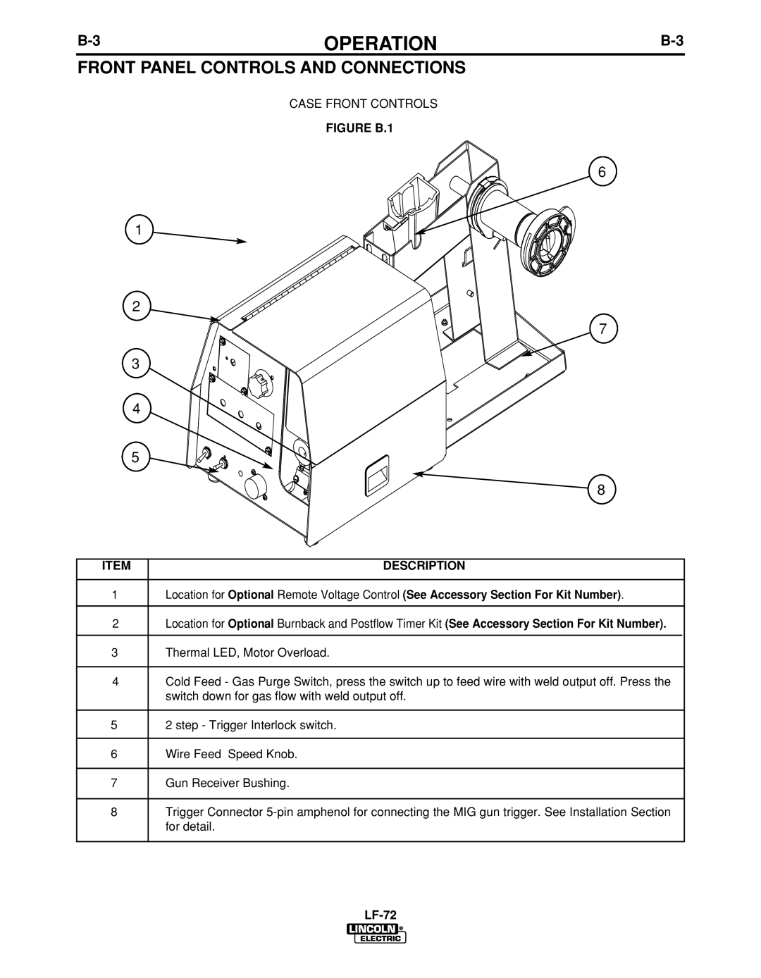
Figure B.1 Description
Front Panel Controls and Connections
Cold FEED/GAS Purge Switch
Burnback and Postflow Timer KIT
Step Trigger Interlock Switch
Remote Voltage Control KIT
Trigger Connector 5-PIN Amphenol
Wire Feed Speed Knob
GUN Receiver Bushing K1500-2
Trigger Interlock
Optional Kits
Accessories
Optional Kits
Accessories
Key
Maintenance
Maintenance
Routine Maintenance
Periodic Maintenance
For Codes above 11290 use
See Figure D.2
For Codes below 11289 use 9 thru
HOW to USE Troubleshooting Guide
Troubleshooting
Output Problems
Installed
LF-72 Feeder 11075, 11076
Wiring Diagram
L12146-1
LF-72 Feeder for Codes 11209, 11210, 11211
Diagrams
Diagrams
Bench Model Bench Model Standard Duty
Dimension Prints
Bench Model Heavy Duty
Precaucion
Warnung