MAINTENANCE | ||
|
|
|
REPLACEMENT INSTRUCTIONS FOR PCT125M CABLE AND TORCH HEAD ASSEMBLY
![]() WARNING
WARNING
ELECTRIC SHOCK can kill.
•Turn the input power off to the Pro- Cut using the disconnect switch at the fuse box before attempting to replace either the torch head or the cable assembly.
•Only qualified personnel should install, service or use this equipment.
•Read instructions thoroughly before beginning.
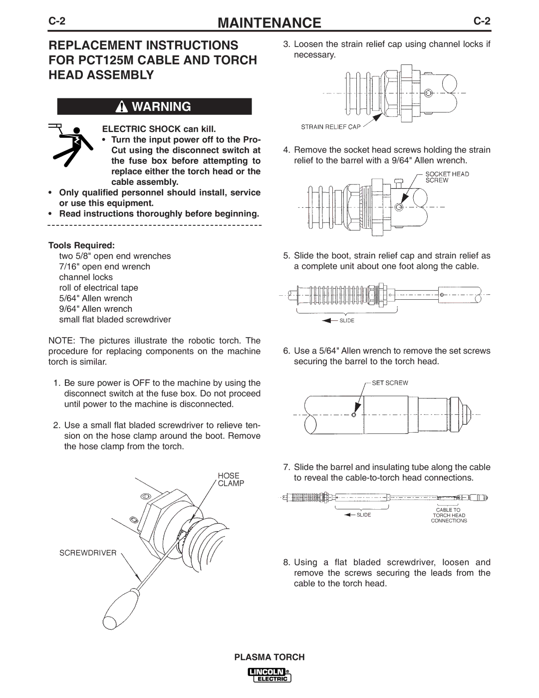
3.Loosen the strain relief cap using channel locks if necessary.
4.Remove the socket head screws holding the strain relief to the barrel with a 9/64" Allen wrench.
Tools Required:
two 5/8" open end wrenches 7/16" open end wrench channel locks
roll of electrical tape 5/64" Allen wrench 9/64" Allen wrench
small flat bladed screwdriver
NOTE: The pictures illustrate the robotic torch. The procedure for replacing components on the machine torch is similar.
1.Be sure power is OFF to the machine by using the disconnect switch at the fuse box. Do not proceed until power to the machine is disconnected.
2.Use a small flat bladed screwdriver to relieve ten- sion on the hose clamp around the boot. Remove the hose clamp from the torch.
5.Slide the boot, strain relief cap and strain relief as a complete unit about one foot along the cable.
6.Use a 5/64" Allen wrench to remove the set screws securing the barrel to the torch head.
7.Slide the barrel and insulating tube along the cable to reveal the
8.Using a flat bladed screwdriver, loosen and remove the screws securing the leads from the cable to the torch head.
PLASMA TORCH
