OPERATION | ||
|
|
|
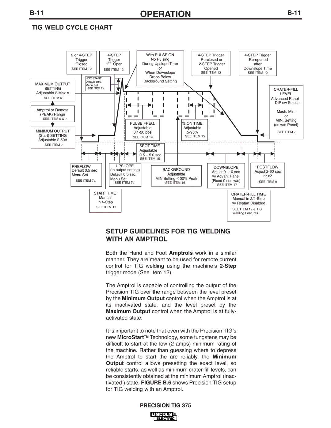
TIG WELD CYCLE CHART
SEE ITEM 12 | SEE ITEM 12 |
| SEE ITEM 12 | SEE ITEM 12 |
|
|
| ||
SEE ITEM 7a |
|
|
| |
SEE ITEM 6 |
|
|
|
|
SEE ITEM 6 & 7 |
|
|
|
|
|
|
|
| SEE ITEM 7 |
| SEE ITEM 14 |
| SEE ITEM 15 |
|
SEE ITEM 7 |
|
|
|
|
| SEE ITEM 15 |
|
|
|
SEE ITEM 7a | SEE ITEM 7a | SEE ITEM 16 |
| SEE ITEM 9 |
|
| |||
|
|
| SEE ITEM 17 | |
| SEE ITEM 12 |
|
| SEE ITEM 12 & TIG |
|
|
|
| |
|
|
|
| Welding Features |
SETUP GUIDELINES FOR TIG WELDING
WITH AN AMPTROL
Both the Hand and Foot Amptrols work in a similar manner. They are meant to be used for remote current control for TIG welding using the machineʼs
The Amptrol is capable of controlling the output of the Precision TIG over the range between the level preset by the Minimum Output control when the Amptrol is at its inactivated state, and the level preset by the Maximum Output control when the Amptrol is at fully- activated state.
It is important to note that even with the Precision TIGʼs new MicroStartTM Technology, some tungstens may be difficult to start at the low (2 amps) minimum rating of the machine. Rather than guessing where to depress the Amptrol to start the arc reliably, the Minimum Output control allows presetting the exact level, so reliable starts, as well as minimum
