OPERATION | ||
|
|
|
FIGURE B.6
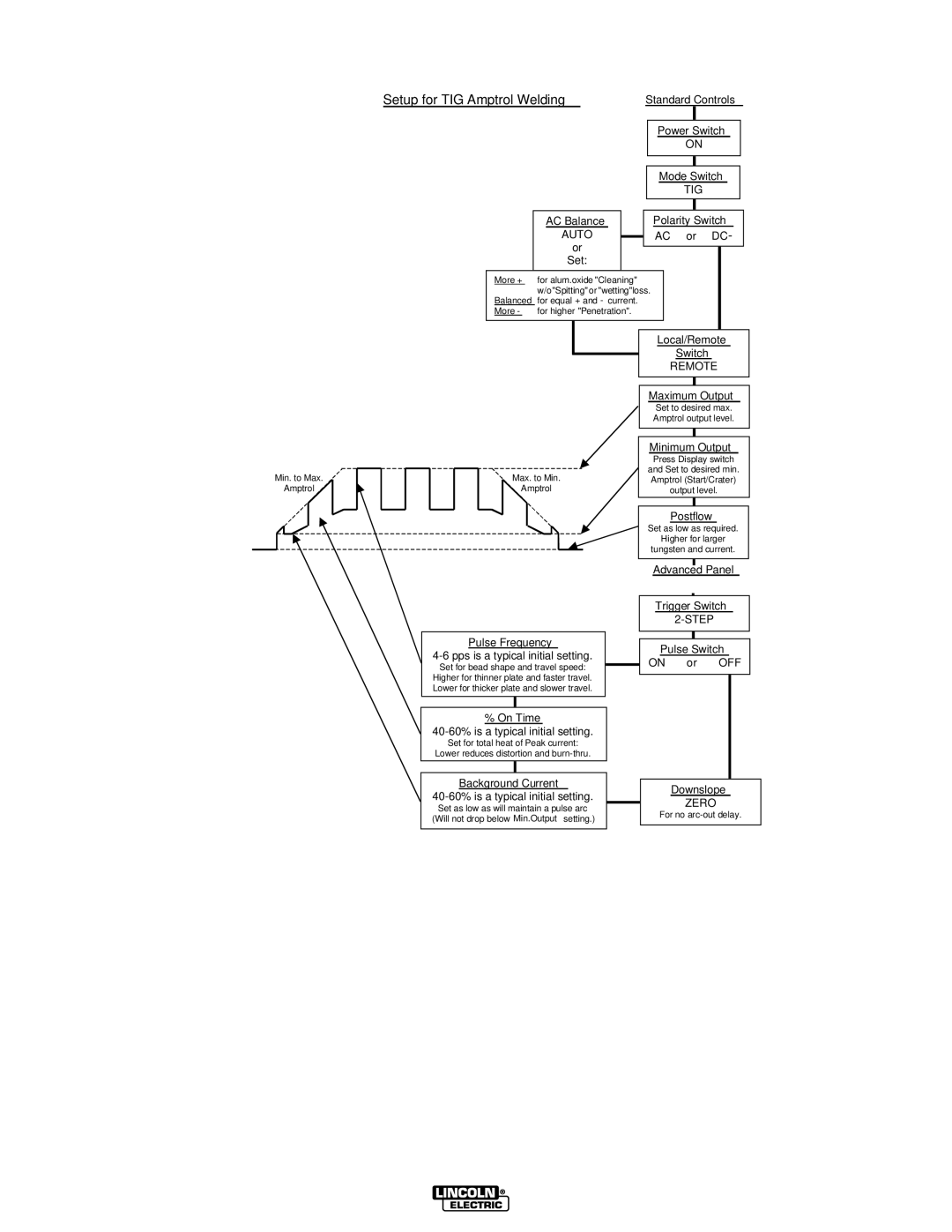
Setup for TIG Amptrol Welding | Standard Controls |
AC Balance
AUTO
or
Set:
Power Switch
ON
Mode Switch
TIG
Polarity Switch
AC or DC-
More + for alum.oxide "Cleaning" w/o"Spitting" or "wetting"loss.
Balanced for equal + and - current. More - for higher "Penetration".
Min. to Max. ![]() Amptrol
Amptrol ![]()
Max. to Min.
Amptrol
Pulse Frequency
4-6 pps is a typical initial setting.
Set for bead shape and travel speed: Higher for thinner plate and faster travel. Lower for thicker plate and slower travel.
% On Time
Set for total heat of Peak current:
Lower reduces distortion and
Background Current
Set as low as will maintain a pulse arc (Will not drop below Min.Output setting.)
Local/Remote
Switch
REMOTE
Maximum Output
Set to desired max. Amptrol output level.
Minimum Output
Press Display switch
and Set to desired min. Amptrol (Start/Crater) output level.
Postflow
Set as low as required.
Higher for larger
tungsten and current.
Advanced Panel
Trigger Switch
Pulse Switch
ON or OFF
Downslope
ZERO
For no