INSTALLATION | ||
|
|
|
3.Be sure the torch and work cable rubber coverings are free of cuts and cracks that allow high frequen- cy leakage. Cables with high natural rubber content, such as Lincoln
4.Keep the torch in good repair and all connections tight to reduce high frequency leakage.
5.The work terminal must be connected to a ground within ten feet of the welder, using one of the fol- lowing methods:
•A metal underground water pipe in direct contact with the earth for ten feet or more.
•A 3/4" (19 mm) galvanized pipe or a 5/8" (16 mm) solid galvanized iron, steel or copper rod driven at least eight feet into the ground.
The ground should be securely made and the ground- ing cable should be as short as possible using cable of the same size as the work cable, or larger. Grounding to the building frame electrical conduit or a long pipe system can result in
INPUT and GROUNDING CONNECTIONS
![]() WARNING
WARNING
ELECTRIC SHOCK can kill.
•Turn the input power OFF at the disconnect switch or fuse box before working on this equipment.
Be sure the voltage, phase, and frequency of the input power is as specified on the rating plate, located on the rear of the machine.
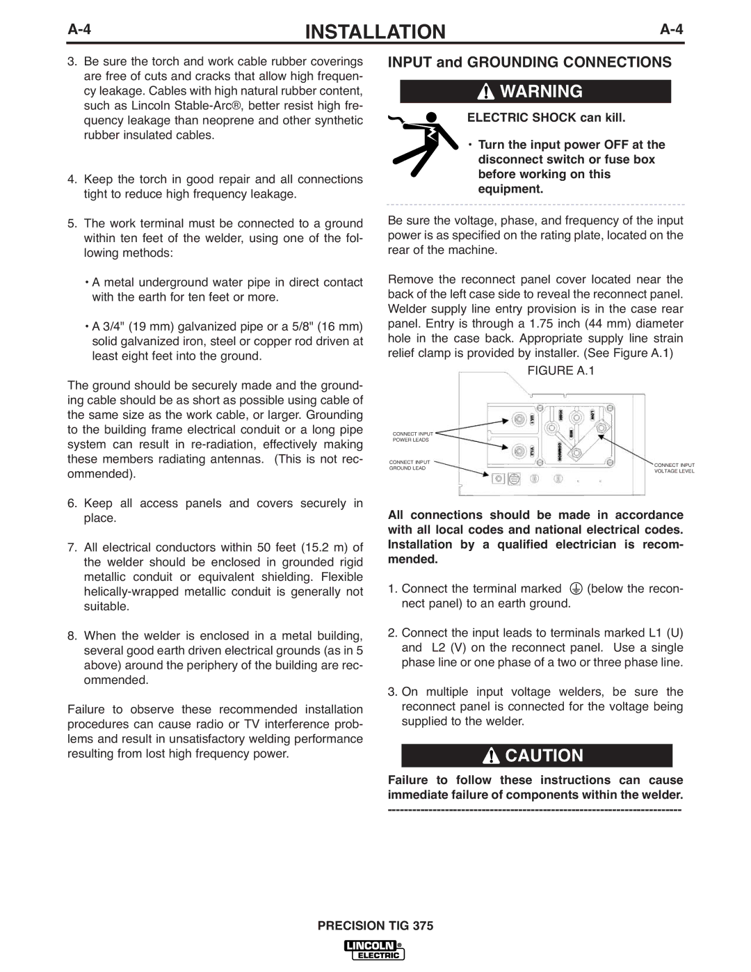
Remove the reconnect panel cover located near the back of the left case side to reveal the reconnect panel. Welder supply line entry provision is in the case rear panel. Entry is through a 1.75 inch (44 mm) diameter hole in the case back. Appropriate supply line strain relief clamp is provided by installer. (See Figure A.1)
FIGURE A.1
CONNECT INPUT
POWER LEADS
CONNECT INPUT
ommended).
GROUND LEAD
CONNECT INPUT
VOLTAGE LEVEL
6.Keep all access panels and covers securely in place.
7.All electrical conductors within 50 feet (15.2 m) of the welder should be enclosed in grounded rigid metallic conduit or equivalent shielding. Flexible
8.When the welder is enclosed in a metal building, several good earth driven electrical grounds (as in 5 above) around the periphery of the building are rec- ommended.
Failure to observe these recommended installation procedures can cause radio or TV interference prob- lems and result in unsatisfactory welding performance resulting from lost high frequency power.
All connections should be made in accordance with all local codes and national electrical codes. Installation by a qualified electrician is recom- mended.
1.Connect the terminal marked ![]() (below the recon- nect panel) to an earth ground.
(below the recon- nect panel) to an earth ground.
2.Connect the input leads to terminals marked L1 (U) and L2 (V) on the reconnect panel. Use a single phase line or one phase of a two or three phase line.
3.On multiple input voltage welders, be sure the reconnect panel is connected for the voltage being supplied to the welder.
![]() CAUTION
CAUTION
Failure to follow these instructions can cause immediate failure of components within the welder.