Wiring Information
Cables and Wiring
Excellent locations to run cables include:
•Roof space
•False ceilings/ bulkhead area
•Through and/or around external walls
•Under floors (subject to access being available)
•Underground in conduit
✓NOTE: Keep Intercom cables far from any AC wiring. Avoid running intercom cable in parallel to AC or any other type of wiring. Avoid placing joins or splices in cables. Locate cables where there is access for future servicing.
Maximum Length for Cable Runs
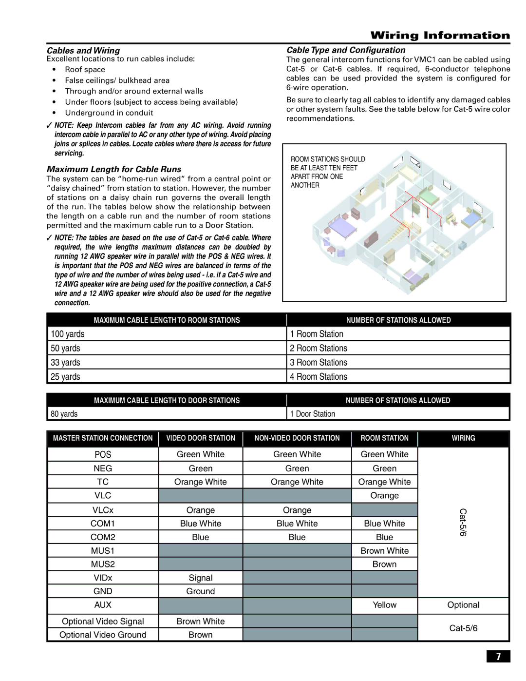
The system can be
✓NOTE: The tables are based on the use of
Cable Type and Configuration
The general intercom functions for VMC1 can be cabled using
Be sure to clearly tag all cables to identify any damaged cables or other system faults. See the table below for
ROOM STATIONS SHOULD
BE AT LEAST TEN FEET
APART FROM ONE
ANOTHER
MAXIMUM CABLE LENGTH TO ROOM STATIONS
NUMBER OF STATIONS ALLOWED
100yards
50yards
33yards
25yards
1 Room Station
2 Room Stations
3 Room Stations
4 Room Stations
MAXIMUM CABLE LENGTH TO DOOR STATIONS
NUMBER OF STATIONS ALLOWED
80 yards
1 Door Station
MASTER STATION CONNECTION |
| VIDEO DOOR STATION |
|
| ROOM STATION |
| |
POS |
| Green White |
| Green White |
| Green White |
|
|
|
|
| ||||
NEG |
| Green |
| Green |
| Green |
|
TC |
| Orange White |
| Orange White |
| Orange White |
|
VLC |
|
|
|
|
| Orange |
|
|
|
|
|
|
|
|
|
VLCx |
| Orange |
| Orange |
|
|
|
|
|
|
|
|
|
|
|
COM1 |
| Blue White |
| Blue White |
| Blue White |
|
|
|
|
|
|
|
|
|
COM2 |
| Blue |
| Blue |
| Blue |
|
|
|
|
|
|
|
|
|
MUS1 |
|
|
|
|
| Brown White |
|
|
|
|
|
|
|
|
|
MUS2 |
|
|
|
|
| Brown |
|
|
|
|
|
|
|
|
|
VIDx |
| Signal |
|
|
|
|
|
|
|
|
|
|
|
|
|
GND |
| Ground |
|
|
|
|
|
AUX |
|
|
|
|
| Yellow |
|
Optional Video Signal |
| Brown White |
|
|
|
|
|
|
|
|
|
|
|
|
|
Optional Video Ground |
| Brown |
|
|
|
|
|
|
|
|
|
|
|
|
|
WIRING
Optional
7
