Do not subject the combination gas valve to inlet gas pressures of more than 14.0” W.C. - natural gas. A service regulator is necessary if higher gas pressures are encountered. Manifold gas pressure in inches of water column is 3.5.
The gas pressure specified refers to flow pressure taken at pressure tap of automatic gas valve while heater is operating.
HEATER WIRING
All electrical work must be installed in accordance with the latest version of the National Electrical Code ANSI/NFPA No. 70,
must conform to all local code authority having jurisdiction. AN
ELECTRICAL GROUND IS REQUIRED TO REDUCE RISK OF ELECTRICAL SHOCK OR POSSIBLE ELECTROCUTION.
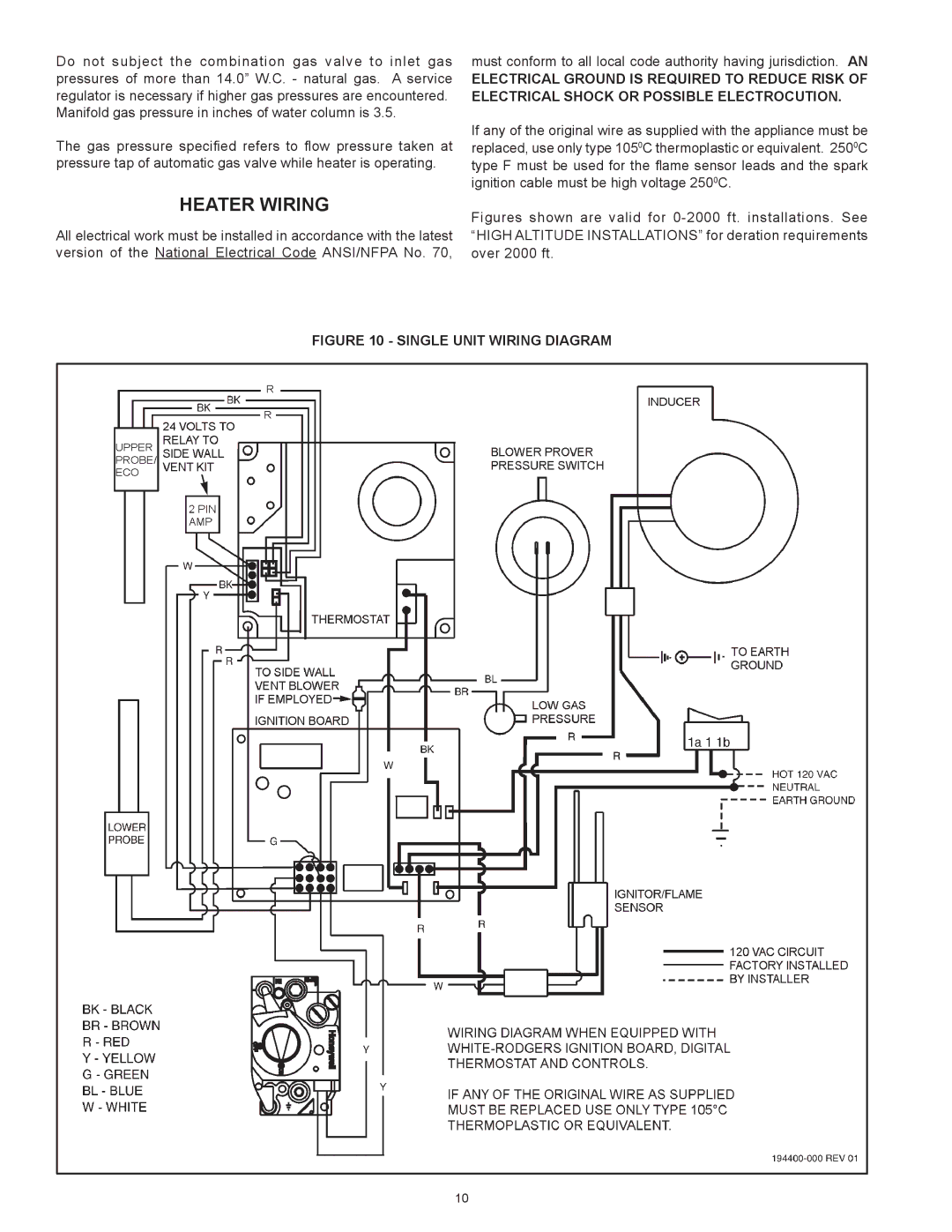
If any of the original wire as supplied with the appliance must be replaced, use only type 1050C thermoplastic or equivalent. 2500C type F must be used for the flame sensor leads and the spark ignition cable must be high voltage 2500C.
Figures shown are valid for 0-2000 ft. installations. See “HIGH ALTITUDE INSTALLATIONS” for deration requirements over 2000 ft.
FIGURE 10 - SINGLE UNIT WIRING DIAGRAM
10