Johnson Controls GG9S'MP Wiring Diagram - 95% Single-StageFurnace, Section Xiii Wiring, Legende

Models: GG9S'MP TG9S'MP

1 40
Download 40 pages 49.32 Kb
Page 39
Image 39
Wiring Diagram - 95% Single-Stage Furnace

Johnson Controls Unitary Products

FIGURE 44: Wiring Diagram

Wiring Diagram - 95% Single-Stage Furnace


NO

C


115VAC


DS

COOL


HEAT

MOT


GND

THE 40,000 INPUT


EAC

CAP

FURNACE HAS ONLY


RED - LOW


YEL - MED LOW


BLK - HI


GRN


BRN

SEE NOTE 2

BLU - MED HI

MOT

BRN

WHT


GND


EAC

CAP

DS

BLK

BRN

NO

C

SECTION XIII: WIRING

39

EAC


EAC

ONE ROLLOUT SWITCH

HUM


RED/WHT

HUM

HUM

NEUTRALS

SECTION XIII: WIRINGHUMLegend

WHT 115VAC

WHT


2 1 WHT

HSI


IDM

ROS RED

ROS RED/BLK


HSI


115V

XFMR

YEL


COM


LegendeDIAGRAMManual backgroundPARK PARK

FURNACE CONTOL

4

GRY


3

GRY

2


1


TAN


TAN

IDM


PRI


2 YEL


R

R


24V SEC


1


G

G


GV


C


ROS


ORN/BLK


Y

Y

ROS


PS1

GV

GND


RED/GRN


PS2


NO

C

C NO

PS1

PS2

LS


LS


W

W


NO C

WHT C

NO

ORN

RED

TST


FS

PRP


HUM

WHT


BLU

10

11

12

BRN

24V SEC


115V PRI


7

8

9


COM

4

5

6

BLK

XFMR


1

2

3


GRN


GND

Y/Y2W R G C


Legend


Legende


DS -

Door switch

MOT -

Circulating motor

LS -

Limit switch

DS -

Commutateur de porte

MOT -

Moteur soufflerie

TST -

Thermostat

ROS -

Rollout switch

IDM -

Inducer motor

HUM -

Humidifier

ROS -

Commutateur de roulement

IDM -

D'induct moteur

FS -

Capteur de flame

FS -

Flame sensor

CAP -

Capacitor

XFMR -

Transformer

XFMR - Transformeur

GV -

Soupape de gaz

CAP -

Capaciteur

TST -

Wall thermostat

HSI -

Hot surface igniter

GV -

Gas valve

LS -

Commutateur de limite

HUM -

Humidificateur

EAC -

Filtre électrique

PS1 -

Pressure switch

EAC -

Electronic air cleaner


HSI -

Ignition de surface chaud


PS2 -

Condensate pressure switch


PS1 -

Commutateur de pression


PS2 -

Commutateur de pression, condensation


1. If any of the original wire as supplied with the furnace must be replaced, it must

1. Si l'un des fils d'origine fourni avec ce four doit être remplacé, il doit être remplacé

be replaced with wiring material having a temperature rating of at least

avec le fil ayant un degré de température d'au moins 221 degrés F (105 degrés C ).

221 degrees F (105 degrees C ).


2. Les connexions à grande vitesse du moteur du ventilateur indiqués sont typiques, mais

2. Blower motor speed connections shown are typical, but may vary by model and

peuvent varier selon le modèle et par application.


application.


364665-UWD-F-0212


DIAGRAM

364861-UIM-H-0712

Page 39
Image 39
Johnson Controls GG9S'MP Wiring Diagram - 95% Single-StageFurnace, Section Xiii Wiring, Johnson Controls Unitary Products

FAQ

What is included in the wiring diagram?

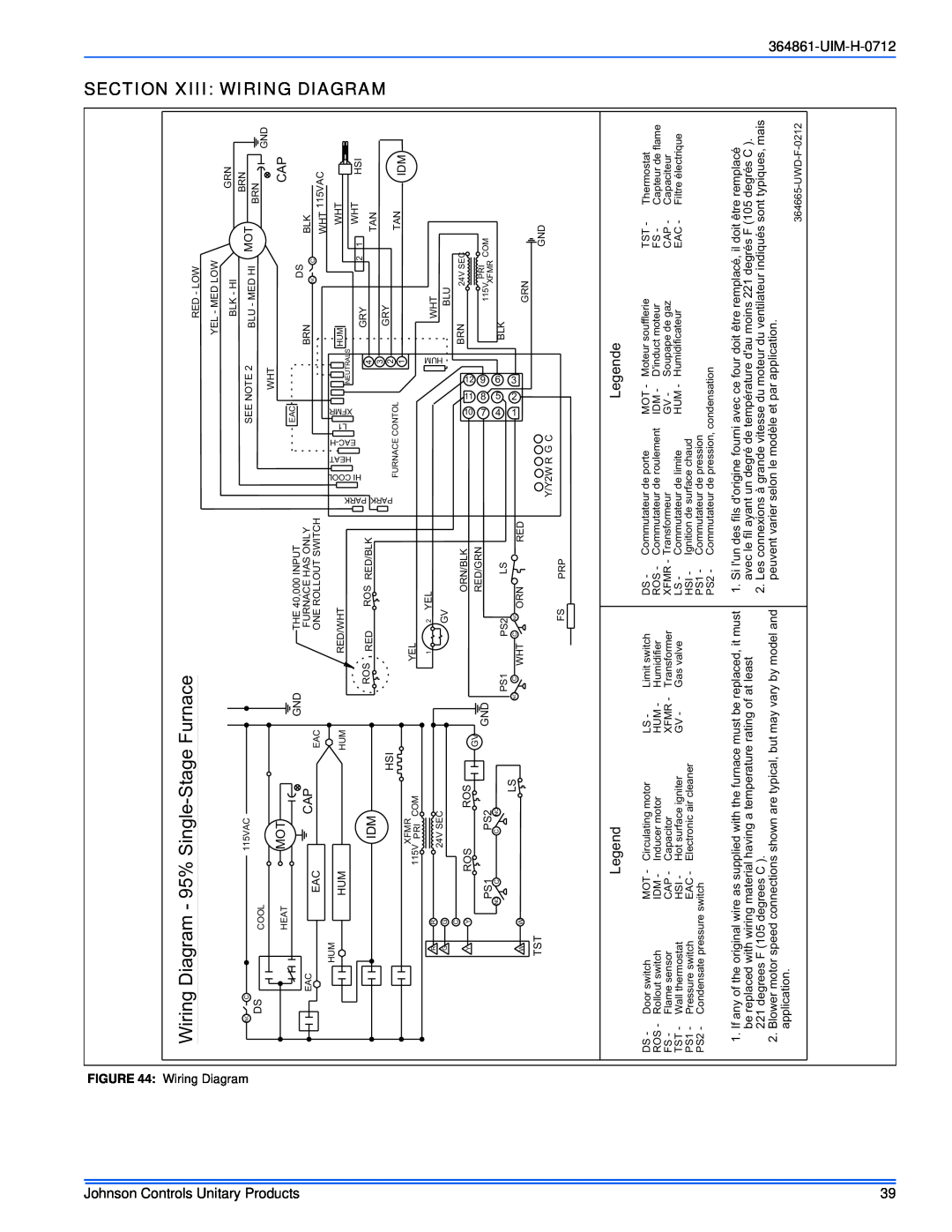
The wiring diagram includes details for connecting various components such as the circulating motor, thermostat, hot surface igniter, gas valve, and more.

Are the blower motor speed connections shown typical for all models?

Blower motor speed connections shown are typical but may vary by model and application.

What temperature rating should replacement wiring material have?

Any replacement wiring material must have a temperature rating of at least 221 degrees F (105 degrees C).