ADJUSTMENT OF TEMPERATURE RISE

364861-UIM-H-0712

MANIFOLD PRESSURE “U” TUBE CONNECTION


OUTLET


PRESSURE TAP


GAS VALVE

1/4” TUBING


FLAME


MAINIFOLD


PIPE

SENSOR


3.5 IN


WATER


COLUMN

GAS


GAS


U-TUBE

PRESSURE

BURNERS


MANOMETER

SHOWN


FIGURE 42: Reading Gas Pressure

After about 5 minutes of operation, determine the furnace temperature rise. Take readings of both the return air and the heated air in the ducts, about six feet (1.8 m) from the furnace where they will not be affected by radiant heat. Increase the blower speed to decrease the temperature rise; decrease the blower speed to increase the rise.

All direct-drive blowers have multi-speed motors. The blower motor speed taps are located on the furnace control board in the blower com- partment. Refer to Figure 42, and the unit-wiring label to change the blower speed. To use the same speed tap for heating and cooling, the heat terminal and cool terminal must be connected using a jumper wire and connected to the desired motor lead. Place all unused motor leads on Park terminals. Two park terminals are provided.

Do not energize more than one motor speed at a time or damage to the motor will result.

ADJUSTMENT OF TEMPERATURE RISE

ADJUSTMENT OF FAN CONTROL SETTINGSManual backgroundDANGER

The temperature rise, or temperature difference between the return air and the supply (heated) air from the furnace, must be within the range shown on the furnace rating plate and within the application limitations shown in Table 6.

The supply air temperature cannot exceed the “Maximum Supply Air Temperature” specified in these instructions and on the furnace rating plate. Under NO circumstances can the furnace be allowed to operate above the Maximum Supply Air Temperature. Operating the furnace above the Maximum Supply Air Temperature will cause pre- mature heat exchanger failure, high levels of Carbon Monoxide, a fire hazard, personal injury, property damage, and/or death.

ADJUSTMENT OF FAN CONTROL SETTINGS

This furnace is equipped with a time-on/time-off heating fan control. The fan on delay is fixed at 30 seconds. The fan off delay has 4 settings (60, 90, 120 and 180 seconds). The fan off delay is factory set to 120 sec- onds. The fan-off setting must be long enough to adequately cool the furnace, but not so long that cold air is blown into the heated space. The fan-off timing may be adjusted by positioning the jumper on two of the four pins as shown in Figure 42.

Blower Off Delay Timer Adjustment Jumper (in seconds)

TWIN


PARK

PARK

180

120

90

60

HI COOL


DELAY

BLOWER OFF


Y/Y2


HEAT


W


EAC-H


R


G


L1


C


XFMR


NEUTRALS


HUM


FIGURE 43: Furnace Control Board

Johnson Controls Unitary Products

33

Page 33
Image 33
Johnson Controls GG9S'MP, TG9S'MP Danger, UIM-H-0712, Adjustment Of Temperature Rise, Adjustment Of Fan Control Settings

FAQ

What is the danger of operating the furnace above the Maximum Supply Air Temperature?

Operating the furnace above the Maximum Supply Air Temperature can cause premature heat exchanger failure, high levels of Carbon Monoxide, a fire hazard, personal injury, property damage, and/or death.

How can I adjust the fan control settings on the furnace?

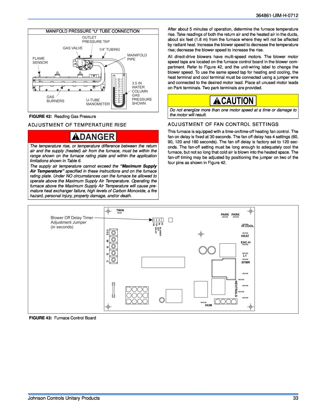
The fan-off timing can be adjusted by positioning the jumper on two of the four pins as shown in Figure 42 on the furnace.

What are the readings needed to determine furnace temperature rise?

After about 5 minutes of operation, determine the furnace temperature rise by taking readings of both the return air and the heated air in the ducts, about six feet from the furnace where they will not be affected by radiant heat.