Johnson Controls TG9S'MP UIM-H-0712, Vent Clearances, Home Layout, Canadian Installations1,3

Models: GG9S'MP TG9S'MP

1 40
Download 40 pages 49.32 Kb
Page 24
Image 24
VENT CLEARANCES

364861-UIM-H-0712

VENT CLEARANCES

D


FIXED


E

CLOSED

V


L

V

B


C


V


F

V


B


FIGURE 30: Home Layout

FIXED GCLOSED

V

A

FIGURE 30: Home Layout H

Direct Vent Terminal Clearances B BCanadian Installations1,3

BI


V

M

V

X


V


B

J


OPERABLE

X

V

K US Installation2,3

FIXED CLOSED

VVENT TERMINAL

XAIR SUPPLY

AREA WHERE TERMINAL IS NOT PERMITTED

Direct Vent Terminal Clearances

Canadian Installations1,3

US Installation2,3

A. Clearance above grade, veranda, porch, deck, or

12” (30.5 cm)

12” (30.5 cm)


balcony


B. Clearance to window or door that may be opened

12” (30.5 cm) for models 100,000 BTUH (30 kW),

Two-pipe (direct vent) applications: 12” (30.5 cm)††

36” (91.4 cm) for models >100,000 BTUH (30 kW).

Single-pipe applications: 4 feet (1.2 m).


C. Clearance to permanently closed window

12” (30.5 cm)

12” (30.5 cm)


D. Vertical clearance to ventilated soffit located

12” (30.5 cm) or in accordance with local installation

12” (30.5 cm) or in accordance with local installation


above the terminal within a horizontal distance


codes and the requirements of the gas supplier.

codes and the requirements of the gas supplier.


of 2 feet (61 cm) from the center line of the terminal


E. Clearance to unventilated soffit

12” (30.5 cm) or in accordance with local installation

12” (30.5 cm) or in accordance with local installation

codes and the requirements of the gas supplier.

codes and the requirements of the gas supplier.


F.

Clearance to outside corner

12” (30.5 cm) or in accordance with local installation

12” (30.5 cm) or in accordance with local installation

codes and the requirements of the gas supplier.

codes and the requirements of the gas supplier.


G. Clearance to inside corner

3 feet (91.4 cm)

3 feet (91.4 cm)


Above a meter/regulator assembly within 3 feet

Above a meter/regulator assembly within 3 feet

H. Clearance to each side of center line

(91.4 cm) horizontally of the vertical center-line of the

(91 cm) horizontally of the vertical center-line of the


extended above meter/regulator assembly

regulator vent outlet to a maximum vertical distance of

regulator vent outlet to a maximum vertical distance of


15 feet (4.5 m) above the meter/regulator assembly.

15 feet (4.5 m) above the meter/regulator assembly.


I.

Clearance to service regulator vent outlet

3 feet (91.4 cm)

3 feet (91.4 cm) or in accordance with local installation

codes and the requirements of the gas supplier.


J. Clearance to non-mechanical air supply inlet to

12” (30.5 cm) for models 100,000 BTUH (30 kW),

Two-pipe (direct vent) applications: 12” (30.5 cm)


building or the combustion air inlet to any other


appliance

36” (91 cm) for models >100,000 BTUH (30 kW).

Single-pipe applications: 4 feet (1.2 m).


K. Clearance to a mechanical supply inlet

6 feet (1.83 m)

3 feet (91.4 cm) above if within 10 feet (3 m)

horizontally.


L.

Clearance above paved sidewalk or paved

7 feet (2.13 m)†

7 feet (2.13 m) or in accordance with local installation


driveway located on public property

codes and the requirements of the gas supplier.


M. Clearance under veranda, porch, deck, or balcony

12” (30.5 cm)‡

12” (30.5 cm) or in accordance with local installation

codes and the requirements of the gas supplier.


1.In accordance with the current CSA B149.1-00, Natural Gas and Propane Installation Code.

2.In accordance with the current ANSI Z223.1 / NFPA 54, National Gas Code.

3.In accordance with the current ANSI Z21.47 * CSA 2.3 American National Standard.

A vent shall not terminate directly above a sidewalk or paved driveway that is located between two single family dwellings and serves both dwellings. †† 12” (30.5 cm) up from the bottom edge of the structure for Two-pipe (direct vent) applications per ANSI Z223.1 / NFPA 54, National Gas Code.

‡ Permitted only if veranda, porch, deck, or balcony is fully open on a minimum of two sides beneath the floor and the distance between the top of the vent termina- tion and the underside of the veranda, porch, or deck is greater than 12” (30.5 cm) as specified in CSA B149.1-00.

A vent shall not terminate less than 12” (30.5 cm) above a grade level.

Any fresh air or make up inlet for dryer or furnace area is considered to be forced air inlet.

Avoid areas where condensate drippage may cause problems such as above planters, patios, or adjacent to windows where steam may cause fogging.

A terminus of a vent shall be fitted with a cap in accordance with the vent manufacturer’s installation instructions, or in accordance with the installation instructions for a special venting system.

Responsibility for the provision of proper adequate venting and air supply for application shall rest with the installer.

Vent shall extend high enough above building, or a neighboring obstruction, so that wind from any direction will not create a positive pressure in the vicinity of the vent.

Consideration must be given for degradation of building materials by flue gases. Sidewall termination may require sealing or shielding of building surfaces with a corrosion resistant material to protect against combustion product corrosion. Consideration must be given to wind direction in order to prevent flue products and/or condensate from being blown against the building surfaces. If a metal shield is used it must be a stainless steel material at a minimum dimension of 20 inches (51 cm). It is recommended that a retaining type collar be used that is attached to the building sur- face to prevent movement of the vent pipe.

24

Johnson Controls Unitary Products

Page 24
Image 24
Johnson Controls TG9S'MP UIM-H-0712, Vent Clearances, Home Layout, Direct Vent Terminal Clearances, US Installation2,3

FAQ

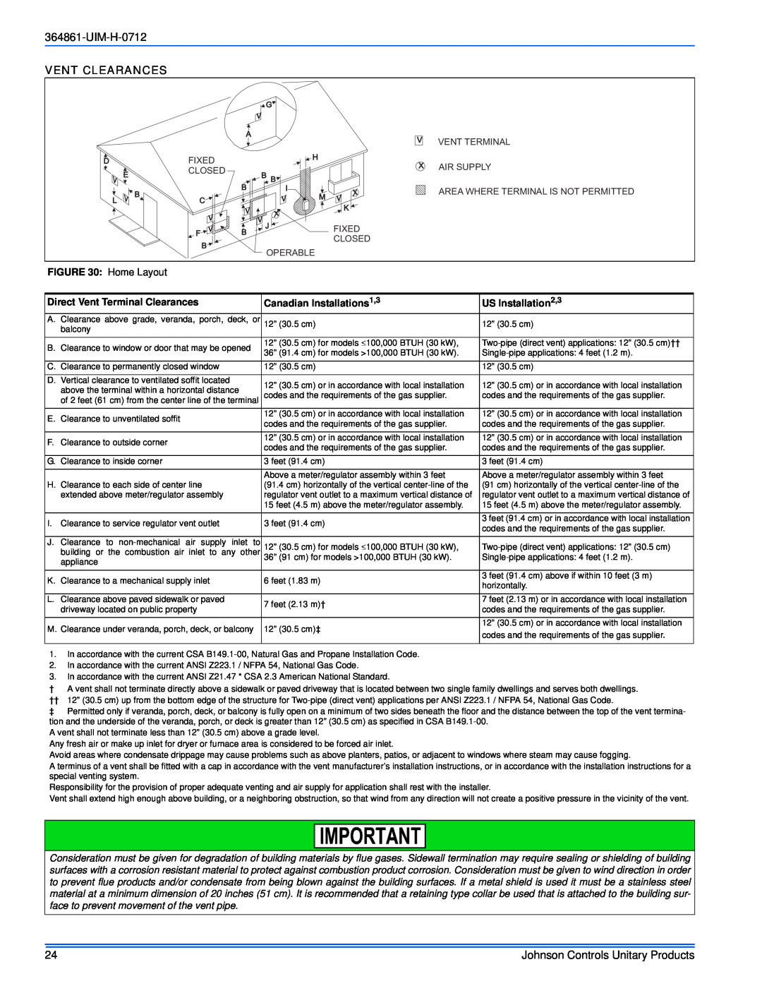
What are the vent clearances for Johnson Controls Furnace models TG9S'MP and GG9S'MP?

The vent clearances for these furnace models are detailed in the official manual, including specific requirements for direct vent terminal clearances and regulations for both Canadian and US installations.

How should a vent termination be fitted for these furnace models?

The terminus of a vent for these furnace models should be fitted with a cap according to the vent manufacturer's installation instructions, or a special venting system's installation instructions.

What is the installer's responsibility regarding venting and air supply for these furnace models?

The installer is responsible for providing proper and adequate venting and air supply for these furnace models, as specified in the official manual.