Optional Equipment | 31 |
Flush Kit
This kit allows the Freedom insert to be installed with more of the unit inside the fireplace (flush) rather than extended onto the hearth. The flush kit must be installed prior to installing the surround panels or placing the insert. Place the insert 24" onto the hearth before following the instructions below.
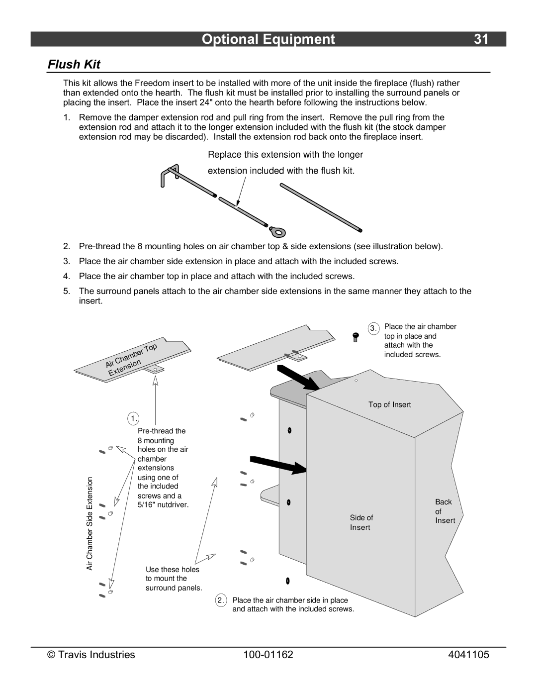
1.Remove the damper extension rod and pull ring from the insert. Remove the pull ring from the extension rod and attach it to the longer extension included with the flush kit (the stock damper extension rod may be discarded). Install the extension rod back onto the fireplace insert.
Replace this extension with the longer
extension included with the flush kit.
2.
3.Place the air chamber side extension in place and attach with the included screws.
4.Place the air chamber top in place and attach with the included screws.
5.The surround panels attach to the air chamber side extensions in the same manner they attach to the insert.
Top
Chamber
![]() AirExtension
AirExtension
|
|
|
|
| 1. | |||||
|
|
|
|
|
|
|
|
|
| |
|
|
|
|
|
|
|
|
|
| |
|
|
|
|
|
|
|
|
|
| 8 mounting |
|
|
|
|
|
|
|
|
|
| |
|
|
|
|
|
|
|
|
|
| holes on the air |
|
|
|
|
|
|
|
|
|
| chamber |
|
|
|
|
|
|
|
|
|
| extensions |
| Extension |
|
|
|
|
|
| using one of | ||
|
|
|
|
|
|
| 5/16" nutdriver. | |||
|
|
|
|
|
|
|
|
|
| the included |
|
|
|
|
|
|
|
|
|
| screws and a |
|
|
|
|
|
|
|
|
|
|
|
|
|
|
|
|
|
|
|
|
|
|
|
| Air Chamber Side |
|
|
|
|
|
|
| Use these holes |
|
|
|
|
|
|
|
|
| ||
|
|
|
|
|
|
|
| |||
|
|
|
|
|
|
|
|
|
| |
|
|
|
|
|
|
|
|
|
| to mount the |
|
|
|
|
|
|
|
|
|
| surround panels. |
|
|
|
|
|
|
|
|
|
| |
|
|
|
|
|
|
|
|
|
|
|
|
|
|
|
|
|
|
|
|
|
|
3. Place the air chamber top in place and attach with the included screws.
Top of Insert
|
|
|
|
|
|
|
|
|
|
|
| Back |
|
|
|
|
|
|
|
|
|
|
|
| |
|
|
|
|
|
|
|
|
|
|
|
| |
|
|
|
|
|
|
|
|
|
|
|
| |
|
|
|
|
|
|
|
|
|
|
|
| |
|
|
|
|
|
|
|
|
|
|
|
| |
|
|
|
|
|
|
|
|
|
|
|
| |
|
|
|
|
|
|
|
|
|
|
| Side of | of |
|
|
|
|
|
|
|
|
|
|
| ||
|
|
|
|
|
|
|
|
|
|
| Insert | |
|
|
|
|
|
|
|
|
|
|
| Insert | |
|
|
|
|
|
|
|
|
|
|
|
| |
|
|
|
|
|
|
|
|
|
|
|
|
|
|
|
|
|
|
|
|
|
|
|
|
|
|
|
|
|
|
|
|
|
|
|
|
|
|
|
|
|
|
|
|
|
|
|
|
|
|
|
|
|
|
|
|
|
|
|
|
|
|
|
|
|
|
|
|
|
|
|
|
|
|
|
|
|
|
2.Place the air chamber side in place and attach with the included screws.
© Travis Industries | 4041105 |
