Setup precautions
•Before connecting any of your video/audio equipment to the projector, carefully read the owners manual supplied with the equipment once again.
•All cable connections should be made with the entire system devices, including the projector, first turned off.
•Obtain commercial interconnecting cables for devices supplied with no accessory or optional interconnect cables.
•Video signals containing too much jitter may cause the images on the screen to randomly wobble or shake. Inserting a time base corrector (TBC) in the projector's video line will relieve this problem.
•The projector only accepts
•The projector contains
•Some PC models are not compatible with the
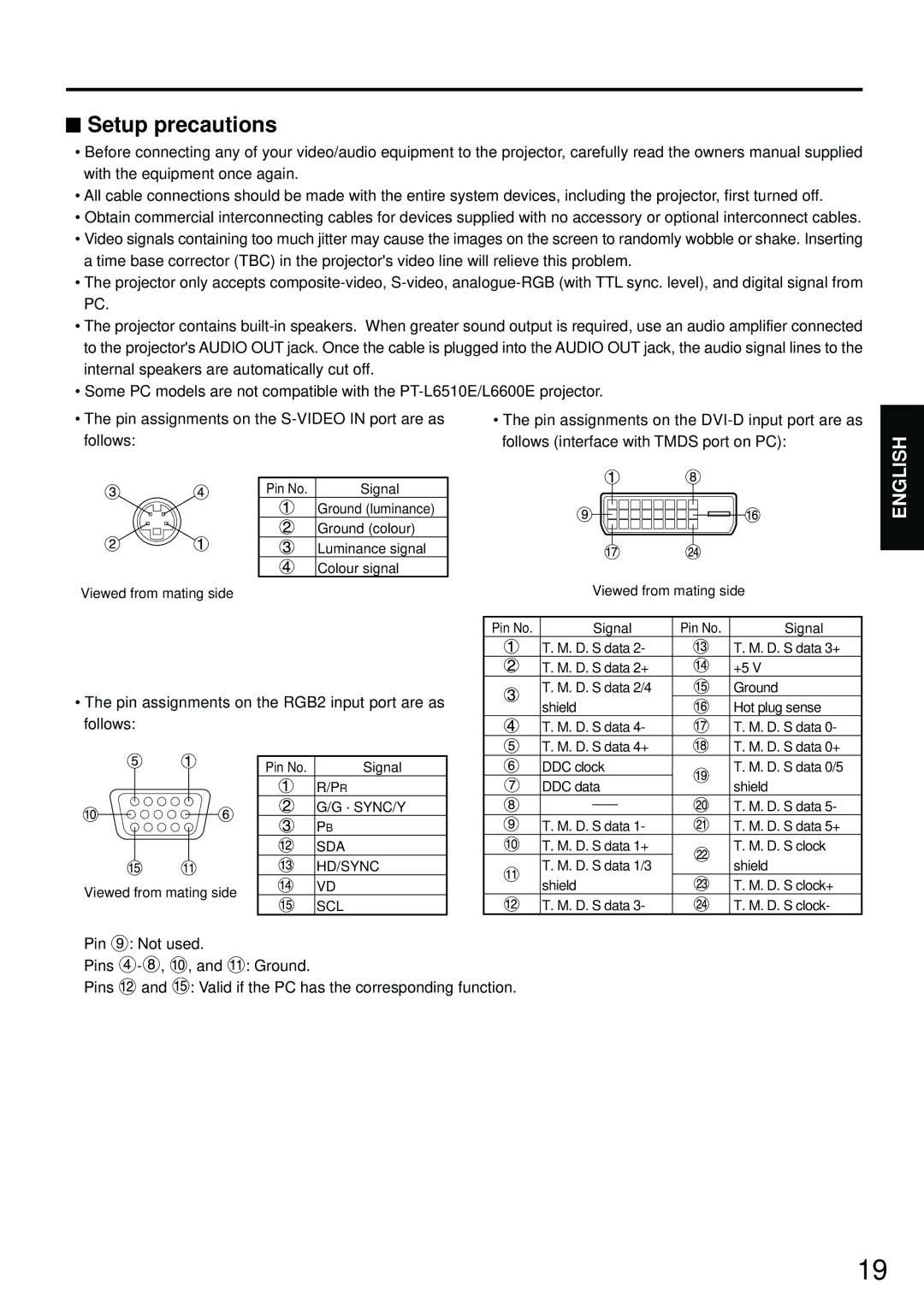
• The pin assignments on the | • The pin assignments on the |
follows: | follows (interface with TMDS port on PC): |
ENGLISH
Pin No. | Signal |
Ground (luminance)
Ground (colour)
Luminance signal
Colour signal
Viewed from mating side
•The pin assignments on the RGB2 input port are as follows:
Viewed from mating side
Pin No. | Signal | Pin No. | Signal |
| T. M. D. S data 2- |
| T. M. D. S data 3+ |
| T. M. D. S data 2+ |
| +5 V |
| T. M. D. S data 2/4 |
| Ground |
| shield |
| Hot plug sense |
| T. M. D. S data 4- |
| T. M. D. S data 0- |
| T. M. D. S data 4+ |
| T. M. D. S data 0+ |
Viewed from mating side
Pin No. | Signal |
| R/PR |
| G/G · SYNC/Y |
| PB |
| SDA |
| HD/SYNC |
| VD |
| SCL |
DDC clock | T. M. D. S data 0/5 | |||
DDC data | shield | |||
|
|
|
| T. M. D. S data 5- |
|
|
|
| |
T. M. D. S data 1- | T. M. D. S data 5+ | |||
T. M. D. S data 1+ | T. M. D. S clock | |||
T. M. D. S data 1/3 |
| shield | ||
shield | T. M. D. S clock+ | |||
T. M. D. S data 3- | T. M. D. S clock- | |||
Pin ![]() : Not used.
: Not used.
Pins ![]() -
-![]() ,
,![]() , and
, and ![]() : Ground.
: Ground.
Pins ![]() and
and ![]() : Valid if the PC has the corresponding function.
: Valid if the PC has the corresponding function.
19