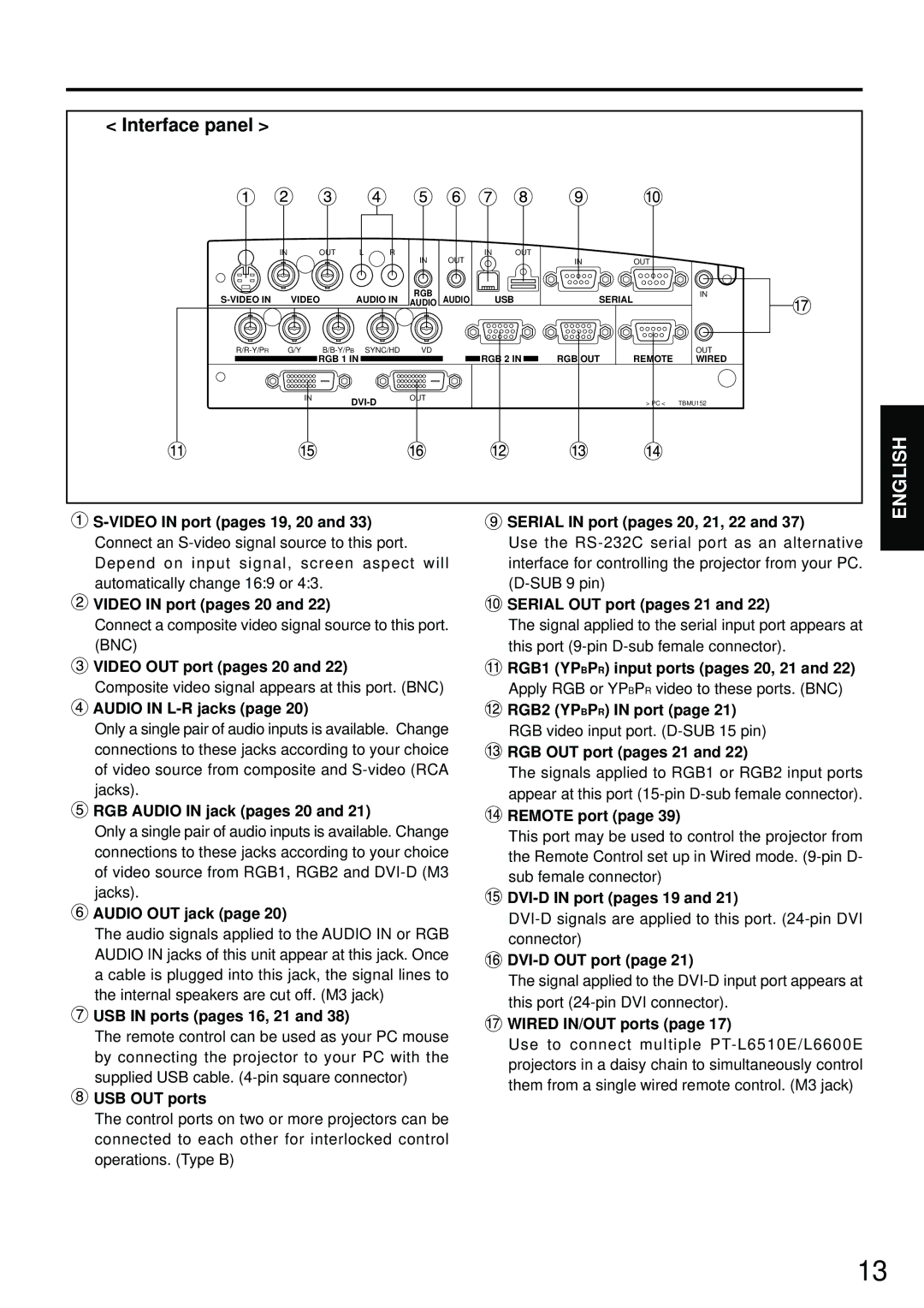
< Interface panel > |
|
|
|
|
|
|
|
|
|
|
|
|
IN |
|
| OUT | L | R | IN | OUT | IN | OUT |
|
|
|
|
|
|
|
|
|
|
| IN | OUT |
| ||
VIDEO | AUDIO IN | RGB | AUDIO |
| USB | SERIAL |
| IN | ||||
AUDIO |
|
|
| |||||||||
G/Y |
|
| SYNC/HD | VD |
|
|
|
|
| OUT | ||
|
|
| RGB 1 IN |
|
|
| RGB 2 IN | RGB OUT | REMOTE | WIRED | ||
|
| IN | OUT |
|
|
|
| > PC < | TBMU152 | |||
|
|
|
|
|
|
|
| |||||
ENGLISH

S-VIDEO IN port (pages 19, 20 and 33)
Connect an
![]() VIDEO IN port (pages 20 and 22)
VIDEO IN port (pages 20 and 22)
Connect a composite video signal source to this port. (BNC)
![]() VIDEO OUT port (pages 20 and 22)
VIDEO OUT port (pages 20 and 22)
Composite video signal appears at this port. (BNC)
 AUDIO IN
 L-R jacks (page 20)
Only a single pair of audio inputs is available. Change connections to these jacks according to your choice of video source from composite and
 RGB AUDIO IN jack (pages 20 and 21)
Only a single pair of audio inputs is available. Change connections to these jacks according to your choice of video source from RGB1, RGB2 and
 AUDIO OUT jack (page 20)
The audio signals applied to the AUDIO IN or RGB AUDIO IN jacks of this unit appear at this jack. Once a cable is plugged into this jack, the signal lines to the internal speakers are cut off. (M3 jack)
 USB IN ports (pages 16, 21 and 38)
The remote control can be used as your PC mouse by connecting the projector to your PC with the supplied USB cable.
 USB OUT ports
The control ports on two or more projectors can be connected to each other for interlocked control operations. (Type B)
 SERIAL IN port (pages 20, 21, 22 and 37)
Use the
![]() SERIAL OUT port (pages 21 and 22)
SERIAL OUT port (pages 21 and 22)
The signal applied to the serial input port appears at this port
![]() RGB1 (YPBPR) input ports (pages 20, 21 and 22)
RGB1 (YPBPR) input ports (pages 20, 21 and 22)
Apply RGB or YPBPR video to these ports. (BNC)
![]() RGB2 (YPBPR) IN port (page 21)
RGB2 (YPBPR) IN port (page 21)
RGB video input port.
 RGB OUT port (pages 21 and 22)
The signals applied to RGB1 or RGB2 input ports appear at this port
 REMOTE port (page 39)
This port may be used to control the projector from the Remote Control set up in Wired mode.
![]()
![]()
The signal applied to the
 WIRED IN/OUT ports (page 17)
Use to connect multiple
13