Front Panel Features | Rear Panel Features |
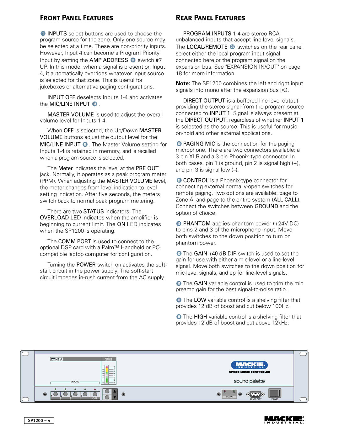
![]() INPUTS select buttons are used to choose the program source for the zone. Only one source may be selected at a time. These are
INPUTS select buttons are used to choose the program source for the zone. Only one source may be selected at a time. These are ![]() switch #7 UP. In this mode, when a signal is present on Input 4, it automatically overrides whatever input source is selected for that zone. This is useful for jukeboxes or alternative paging configurations.
switch #7 UP. In this mode, when a signal is present on Input 4, it automatically overrides whatever input source is selected for that zone. This is useful for jukeboxes or alternative paging configurations.
INPUT OFF deselects Inputs ![]() .
.
MASTER VOLUME is used to adjust the overall volume level for Inputs
When OFF is selected, the Up/Down MASTER VOLUME buttons adjust the output level for the MIC/LINE INPUT ![]() . The Master Volume setting for Inputs
. The Master Volume setting for Inputs
The Meter indicates the level at the PRE OUT
jack. Normally, it operates as a peak program meter (PPM). When adjusting the MASTER VOLUME level, the meter changes from level indication to level setting indication. After five seconds, the meters switch back to normal peak program metering.
There are two STATUS indicators. The OVERLOAD LED indicates when the amplifier is beginning to current limit. The ON LED indicates when the SP1200 is operating.
The COMM PORT is used to connect to the optional DSP card with a Palm™ Handheld or PC- compatible laptop computer for configuration.
Turning the POWER switch on activates the soft- start circuit in the power supply. The
PROGRAM INPUTS
The LOCAL/REMOTE ![]() switches on the rear panel select either the local program input signal connected here or the program signal on the expansion bus. See "EXPANSION IN/OUT" on page 18 for more information.
switches on the rear panel select either the local program input signal connected here or the program signal on the expansion bus. See "EXPANSION IN/OUT" on page 18 for more information.
Note: The SP1200 combines the left and right input signals into mono after the expansion bus I/O.
DIRECT OUTPUT is a buffered
![]() PAGING MIC is the connection for the paging microphone. There are two connectors available: a
PAGING MIC is the connection for the paging microphone. There are two connectors available: a
![]() CONTROL is a
CONTROL is a
![]() PHANTOM applies phantom power (+24V DC) to pins 2 and 3 of the microphone input. Move both switches to the down position to turn on phantom power.
PHANTOM applies phantom power (+24V DC) to pins 2 and 3 of the microphone input. Move both switches to the down position to turn on phantom power.
![]() The GAIN +40 dB DIP switch is used to set the gain for use with either a
The GAIN +40 dB DIP switch is used to set the gain for use with either a
![]() The GAIN variable control is used to trim the mic preamp gain for the best
The GAIN variable control is used to trim the mic preamp gain for the best
![]() The LOW variable control is a shelving filter that provides 12 dB of boost and cut below 100Hz.
The LOW variable control is a shelving filter that provides 12 dB of boost and cut below 100Hz.
![]() The HIGH variable control is a shelving filter that provides 12 dB of boost and cut above 12kHz.
The HIGH variable control is a shelving filter that provides 12 dB of boost and cut above 12kHz.
ZONE A
INPUTS
MASTER
VOLUME
3
0
3
6
9
15
30
55
SP1200 MUSIC CONTROLLER
1 | 2 | 3 | 4 |
OFF
OL ON
STATUS
COMM PORT | POWER |
SP1200 – 4