Connecting the Expansion Bus
These are
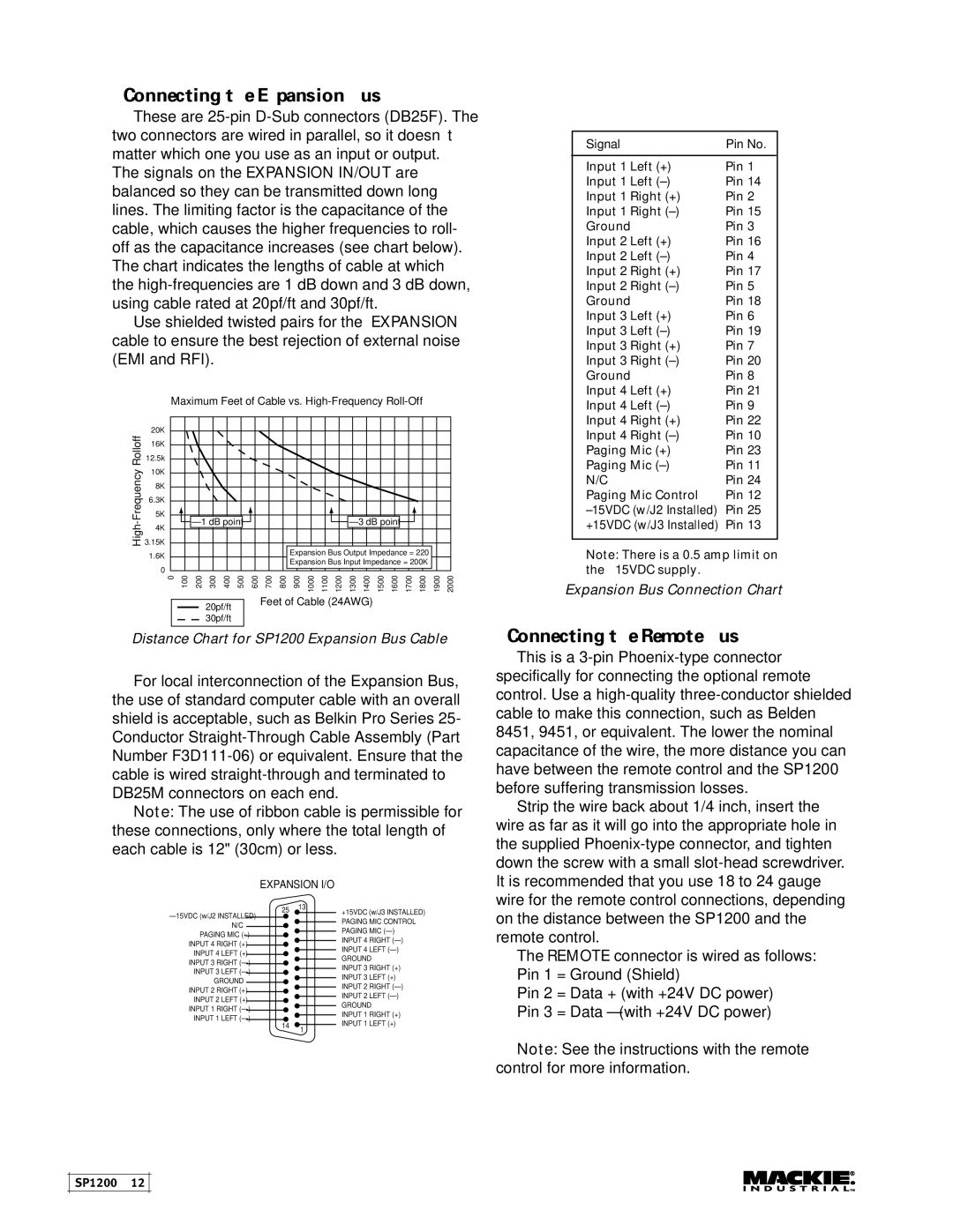
Use shielded twisted pairs for the EXPANSION cable to ensure the best rejection of external noise (EMI and RFI).
| Maximum Feet of Cable vs. | |
| 20K |
|
Rolloff | 16K |
|
12.5k |
| |
10K |
| |
3.15K |
| |
| 8K |
|
| 6.3K |
|
| 5K |
|
| ||
| 4K |
|
1.6K |
|
|
|
|
|
|
|
|
|
|
| Expansion Bus Output Impedance = 220Ω |
|
|
|
| |||||||||
0 |
|
|
|
|
|
|
|
|
|
|
| Expansion Bus Input Impedance = 200KΩ |
|
|
|
| |||||||||
|
|
|
|
|
|
|
|
|
|
|
|
|
|
|
|
|
|
|
|
|
|
|
|
| |
0 | 100 | 200 | 300 | 400 | 500 | 600 | 700 | 800 |
| 900 | 1000 | 1100 | 1200 | 1300 | 1400 | 1500 | 1600 | 1700 | 1800 | 1900 | 2000 | ||||
|
|
|
|
|
|
|
|
| Feet of Cable (24AWG) |
|
|
|
|
|
|
|
|
| |||||||
|
|
|
|
| 20pf/ft |
|
|
|
|
|
|
|
|
|
|
| |||||||||
|
|
|
|
|
|
|
|
|
|
|
|
|
|
|
|
|
|
|
|
|
|
|
| ||
|
|
|
|
| 30pf/ft |
|
|
|
|
|
|
|
|
|
|
|
|
|
|
|
|
|
|
| |
Distance Chart for SP1200 Expansion Bus Cable
For local interconnection of the Expansion Bus, the use of standard computer cable with an overall shield is acceptable, such as Belkin Pro Series 25- Conductor
Note: The use of ribbon cable is permissible for these connections, only where the total length of each cable is 12" (30cm) or less.
EXPANSION I/O
Signal | Pin No. |
|
|
Input 1 Left (+) | Pin 1 |
Input 1 Left | Pin 14 |
Input 1 Right (+) | Pin 2 |
Input 1 Right | Pin 15 |
Ground | Pin 3 |
Input 2 Left (+) | Pin 16 |
Input 2 Left | Pin 4 |
Input 2 Right (+) | Pin 17 |
Input 2 Right | Pin 5 |
Ground | Pin 18 |
Input 3 Left (+) | Pin 6 |
Input 3 Left | Pin 19 |
Input 3 Right (+) | Pin 7 |
Input 3 Right | Pin 20 |
Ground | Pin 8 |
Input 4 Left (+) | Pin 21 |
Input 4 Left | Pin 9 |
Input 4 Right (+) | Pin 22 |
Input 4 Right | Pin 10 |
Paging Mic (+) | Pin 23 |
Paging Mic | Pin 11 |
N/C | Pin 24 |
Paging Mic Control | Pin 12 |
Pin 25 | |
+15VDC (w/J3 Installed) | Pin 13 |
|
|
Note: There is a 0.5 amp limit on the ±15VDC supply.
Expansion Bus Connection Chart
Connecting the Remote Bus
This is a
Strip the wire back about 1/4 inch, insert the wire as far as it will go into the appropriate hole in the supplied
INPUT 4 RIGHT (+)
INPUT 4 LEFT (+)
INPUT 3 RIGHT
INPUT 3 LEFT
GROUND INPUT 2 RIGHT (+)
INPUT 2 LEFT (+)
INPUT 1 RIGHT
INPUT 1 LEFT
25 13
14 ![]() 1
1
+15VDC (w/J3 INSTALLED) PAGING MIC CONTROL PAGING MIC
INPUT 4 RIGHT
INPUT 4 LEFT
GROUND
INPUT 3 RIGHT (+)
INPUT 3 LEFT (+)
INPUT 2 RIGHT
INPUT 2 LEFT
GROUND
INPUT 1 RIGHT (+)
INPUT 1 LEFT (+)
on the distance between the SP1200 and the remote control.
The REMOTE connector is wired as follows: Pin 1 = Ground (Shield)
Pin 2 = Data + (with +24V DC power) Pin 3 = Data – (with +24V DC power)
Note: See the instructions with the remote control for more information.
SP1200 – 12