Using the EQ
Each local MIC/LINE INPUT has a
Using the PRE OUT/AMP IN
Connections
The PRE OUT and AMP IN connectors are provided to give you more flexibility in your system design. The SP1200 is shipped with
This also provides a point in the signal chain to insert an external signal processor. Simply connect the
Another option that is available is to connect another amplifier into the system. Simply use a
Zone A Output
The amplifier output on the SP1200 can be used with an
Direct Speaker Connection
If the SP1200 is not being used in a distributed speaker system, you can reconfigure the amplifier to drive an
Distributed Speaker System
When using the SP1200 in a 70V or 100V system, connect the speaker output directly to the distributed system. The SP1200 can directly drive a distributed system's speaker line without the need for an output transformer. The SP1200 can supply up to 200 watts into a 70V or 100V distributed system. Make sure the taps on the speakers in the system do not exceed a total of 200 watts.
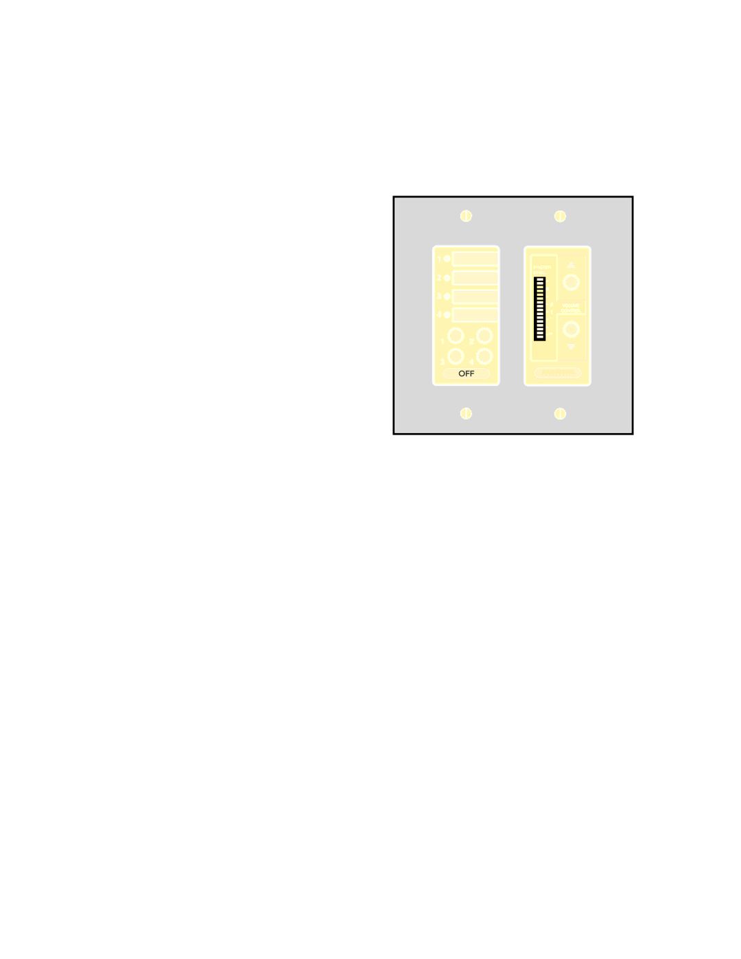
Using the Remote Connection
The optional SP1200 Remote Control
MASTER
LEVEL
![]()
![]() 3
3 ![]()
![]() 0
0
![]()
![]() 3
3 ![]()
![]() 6
6
![]()
![]() 9
9 ![]()
![]() 15
15
![]()
![]() 30
30 ![]()
![]() 55
55
Connecting One or More Remote Controls
Each Remote Control affects only the zone to which it is connected. Up to ten remote controls may be connected to each zone simultaneously. This allows controls to be conveniently placed.
Each control will interact with the SP1200, and all controls will reflect the current source and level settings. Note that the remote control indicates the gain setting and not the actual signal level in real time. In addition, the SP1200 provides a method for controlling two independent zones using a single Remote Control by assigning them to the same AMP ADDRESS (see next section).
The maximum distance between the remotes and the SP1200 varies, depending on the type of cable selected and the number of remote controls used. Typically, a lower wire gauge and cable capacitance allow longer distances. See the instruc- tions with the remote control for more information.
Using the RS485 Connection
The amplifier is equipped with an RS485 connection. When two SP1200s are linked via the RS485 connection and assigned to the same zone (AMP ADDRESS switches
SP1200 – 21