Repair | P 8/ 13 |
|
[3]DISASSEMBLY/ASSEMBLY
[3]-5. Gear case section (cont.)
ASSEMBLING
1)After applying Makita grease N No.2 to teeth of all Spur gears, shafts of Carrier complete B and shafts of Spur gear 9 complete A, assemble Ball bearing 6805LLB and Carrier complete B to Gear case. (Fig. 2) Then assemble Internal gear
47 and Spur gears from the opposite side.
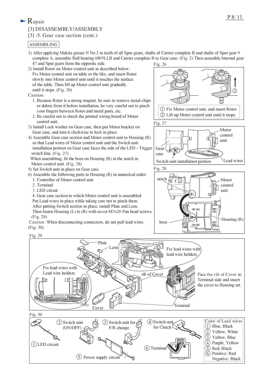
2) Install Rotor on Motor control unit as described below; |
|
| |
Fix Motor control unit on table or the like, and insert Rotor |
|
| |
slowly into Motor control unit until it touches the surface |
|
| |
of the table. Then lift up Motor control unit gradually |
|
| |
until it stops. (Fig. 26) |
|
| |
Caution: |
|
| |
1. Because Rotor is a strong magnet, be sure to remove metal chips |
|
| |
or debris from it before installation, be very careful not to pinch | Fix Motor control unit, and insert Rotor. | ||
your fingers between Rotor and metal parts, etc. | |||
Lift up Motor control unit until it stops. | |||
2. Be careful not to shock the printed wiring board of Motor | |||
control unit. | Fig. 27 |
| |
3) Install Lock washer on Gear case, then put Motor bracket on |
| ||
| Motor | ||
Gear case, and turn it clockwise to lock in place. |
| ||
| control | ||
4) Assemble Gear case section and Motor control unit to Housing (R) |
| ||
| unit | ||
so that Lead wires of Motor control unit and the Switch unit |
| ||
|
| ||
installation portion on Gear case faces the side of the LED - Trigger | Gear |
| |
switch line. (Fig. 27) | case |
| |
When assembling, fit the boss on Housing (R) in the notch in | Switch unit installation portion | Lead wires | |
Motor control unit. (Fig. 28) | |||
Fig. 28 |
| ||
5) Set Switch unit in place on Gear case. |
| ||
6) Assemble the following parts to Housing (R) in numerical order: | notch |
| |
1. Controller of Motor control unit | Motor | ||
2. Terminal |
| control | |
3. LED circuit |
| unit | |
4. Gear case section to which Motor control unit is assembled |
|
| |
Put Lead wires in place while taking care not to pinch them. |
|
| |
After putting Switch section in place, install Plate and Lens. |
|
| |
Then fasten Housing (L) to (R) with seven M3x20 Pan head screws. |
|
| |
(Fig. 29) |
| Housing (R) | |
Caution: When disconnecting connectors, do not pull lead wires. | boss | ||
| |||
(Fig. 30) |
|
| |
Fig. 29 |
|
| |
Plate |
|
| |
Lens | Fix lead wires with |
| |
|
| ||
| lead wire holders. |
| |
Fix lead wires with Lead wire holders.
rib of Cover
Cover
Fig. 30
Switch unit | Switch unit for | Switch unit |
(ON/OFF) | F/R change | for Clutch |
LED circuit |
| Terminal |
|
| |
| Power supply circuit |
|