| P 9 / 13 |
[3] | |
ASSEMBLING | Fig. 28 |
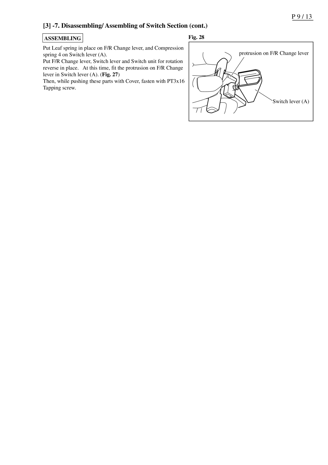
Put Leaf spring in place on F/R Change lever, and Compression | protrusion on F/R Change lever |
spring 4 on Switch lever (A). | |
Put F/R Change lever, Switch lever and Switch unit for rotation |
|
reverse in place. At this time, fit the protrusion on F/R Change |
|
lever in Switch lever (A). (Fig. 27) |
|
Then, while pushing these parts with Cover, fasten with PT3x16 |
|
Tapping screw. |
|
| Switch lever (A) |
