P 5/ 8
 Repair
[2]ASSEMBLY/ DISASSEMBLY
[2]-3. Change lever section
DISASSEMBLING
(1)Remove Cowling. (Refer to the previous page.)
(2)Shift Change lever to the position of grass cutting height 75mm.
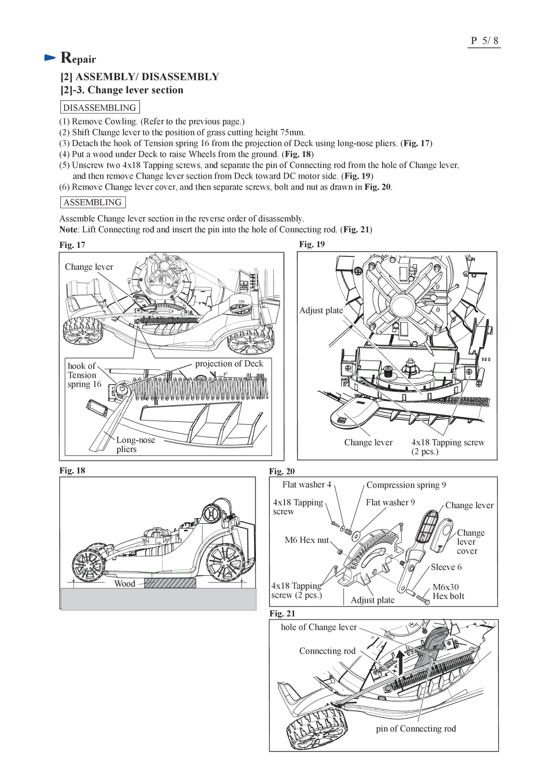
(3)Detach the hook of Tension spring 16 from the projection of Deck using
(4)Put a wood under Deck to raise Wheels from the ground. (Fig. 18)
(5)Unscrew two 4x18 Tapping screws, and separate the pin of Connecting rod from the hole of Change lever, and then remove Change lever section from Deck toward DC motor side. (Fig. 19)
(6)Remove Change lever cover, and then separate screws, bolt and nut as drawn in Fig. 20.
ASSEMBLING
Assemble Change lever section in the reverse order of disassembly.
Note: Lift Connecting rod and insert the pin into the hole of Connecting rod. (Fig. 21)
Fig. 17 | Fig. 19 |
Change lever
hook of | projection of Deck |
Tension |
|
spring 16 |
|
![]()
Fig. 18
Wood ![]()
![]()
![]()
![]()
![]()
![]()
Adjust plate
| Change lever | 4x18 Tapping screw | |
|
| (2 pcs.) | |
Fig. 20 |
|
|
|
Flat washer 4 | Compression spring 9 | ||
4x18 Tapping | Flat washer 9 | Change lever | |
screw |
|
|
|
M6 Hex nut |
|
| Change |
|
| lever | |
|
|
| cover |
|
|
| Sleeve 6 |
4x18 Tapping |
|
| M6x30 |
screw (2 pcs.) | Adjust plate |
| Hex bolt |
|
|
| |
Fig. 21
hole of Change lever
Connecting rod
pin of Connecting rod
