P 3/ 8
 Repair
[2]ASSEMBLY/ DISASSEMBLY
[2]-1. Handle section (cont.)
ASSEMBLING
Assemble Handle section in the reverse order of disassembly.
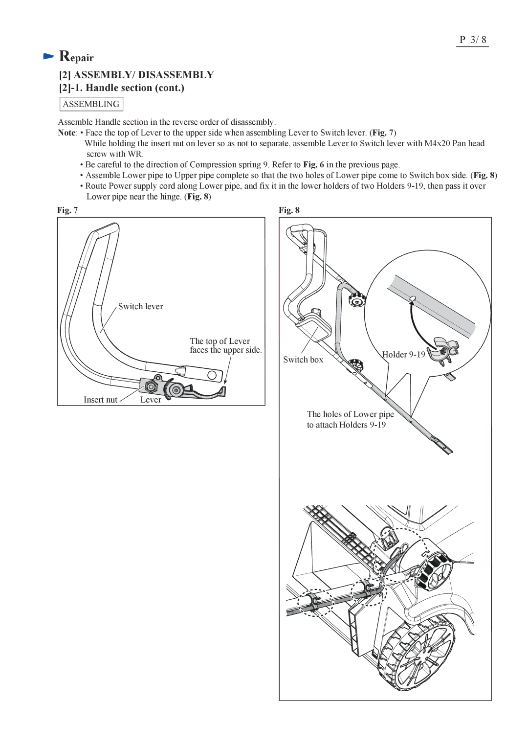
Note: • Face the top of Lever to the upper side when assembling Lever to Switch lever. (Fig. 7)
While holding the insert nut on lever so as not to separate, assemble Lever to Switch lever with M4x20 Pan head screw with WR.
•Be careful to the direction of Compression spring 9. Refer to Fig. 6 in the previous page.
•Assemble Lower pipe to Upper pipe complete so that the two holes of Lower pipe come to Switch box side. (Fig. 8)
•Route Power supply cord along Lower pipe, and fix it in the lower holders of two Holders
Fig. 7 | Fig. 8 |
Switch lever
The top of Lever |
|
|
faces the upper side. | Switch box | Holder |
| ||
|
|
Insert nut | Lever |
The holes of Lower pipe to attach Holders
