P 6/ 8
 Repair
[2]ASSEMBLY/ DISASSEMBLY
[2]-4. Wheels
DISASSEMBLING
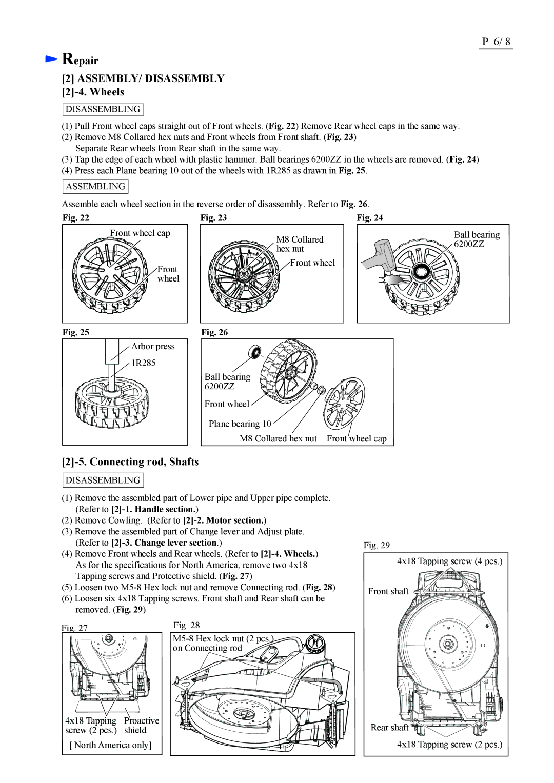
(1)Pull Front wheel caps straight out of Front wheels. (Fig. 22) Remove Rear wheel caps in the same way.
(2)Remove M8 Collared hex nuts and Front wheels from Front shaft. (Fig. 23) Separate Rear wheels from Rear shaft in the same way.
(3)Tap the edge of each wheel with plastic hammer. Ball bearings 6200ZZ in the wheels are removed. (Fig. 24)
(4)Press each Plane bearing 10 out of the wheels with 1R285 as drawn in Fig. 25.
ASSEMBLING
Assemble each wheel section in the reverse order of disassembly. Refer to Fig. 26.
Fig. 22 | Fig. 23 | Fig. 24 |
| Front wheel cap | M8 Collared |
|
| |
|
| hex nut |
| Front | Front wheel |
|
| |
| wheel |
|
Fig. 25 | Fig. 26 |
| Arbor press |
| 1R285 |
| Ball bearing |
| 6200ZZ |
| Front wheel |
| Plane bearing 10 |
| M8 Collared hex nut Front wheel cap |
Ball bearing 6200ZZ
[2]-5. Connecting rod, Shafts
DISASSEMBLING
(1)Remove the assembled part of Lower pipe and Upper pipe complete. (Refer to
(2)Remove Cowling. (Refer to
(3)Remove the assembled part of Change lever and Adjust plate. (Refer to
(4)Remove Front wheels and Rear wheels. (Refer to
(5)Loosen two
(6)Loosen six 4x18 Tapping screws. Front shaft and Rear shaft can be removed. (Fig. 29)
Fig. 29
4x18 Tapping screw (4 pcs.)
Front shaft
Fig. 27
4x18 Tapping Proactive screw (2 pcs.) shield
[ North America only]
Fig. 28
![]()
Rear shaft ![]()
![]() 4x18 Tapping screw (2 pcs.)
4x18 Tapping screw (2 pcs.)
