 Wiring diagram (cont.)
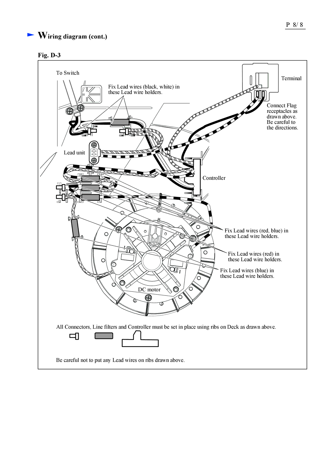
Fig. D-3
To Switch
Fix Lead wires (black, white) in these Lead wire holders.
Lead unit
P 8/ 8
Terminal
Connect Flag receptacles as drawn above. Be careful to the directions.
Controller
Fix Lead wires (red, blue) in these Lead wire holders.
Fix Lead wires (red) in these Lead wire holders.
Fix Lead wires (blue) in these Lead wire holders.
DC motor
All Connectors, Line filters and Controller must be set in place using ribs on Deck as drawn above.
Be careful not to put any Lead wires on ribs drawn above.
