P 6/ 8
 Repair
[3]DISASSEMBLY/ASSEMBLY
[3]-3. Motor Section (cont.)
ASSEMBLING
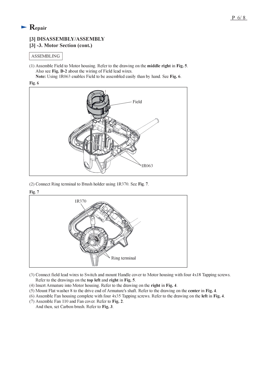
(1)Assemble Field to Motor housing. Refer to the drawing on the middle right in Fig. 5. Also see Fig.
Note: Using 1R063 enables Field to be assembled easily than by hand. See Fig. 6.
Fig. 6
Field |
1R063 |
(2)Connect Ring terminal to Brush holder using 1R370. See Fig. 7.
Fig. 7
1R370 |
Ring terminal |
(3)Connect field lead wires to Switch and mount Handle cover to Motor housing with four 4x18 Tapping screws. Refer to the drawings on the top left and right in Fig. 5.
(4)Insert Armature into Motor housing. Refer to the drawing on the right in Fig. 4.
(5)Mount Flat washer 8 to the drive end of Armature's shaft. Refer to the drawing on the center in Fig. 4.
(6)Assemble Fan housing complete with four 4x35 Tapping screws. Refer to the drawing on the left in Fig. 4.
(7)Assemble Fan 110 and Fan cover. Refer to Fig. 2. And then, set Carbon brush. Refer to Fig. 3.