P 7/ 8
 Circuit diagram
Fig. D-1
|
| Color index of lead wires' sheath | |||||||||
Black |
|
|
|
|
| Blue |
|
|
|
|
|
|
|
|
|
| |||||||
|
|
|
|
| |||||||
White |
|
|
|
|
| Brown |
|
|
|
|
|
|
|
|
|
|
|
|
| ||||
|
|
|
|
|
|
|
|
|
|
|
|
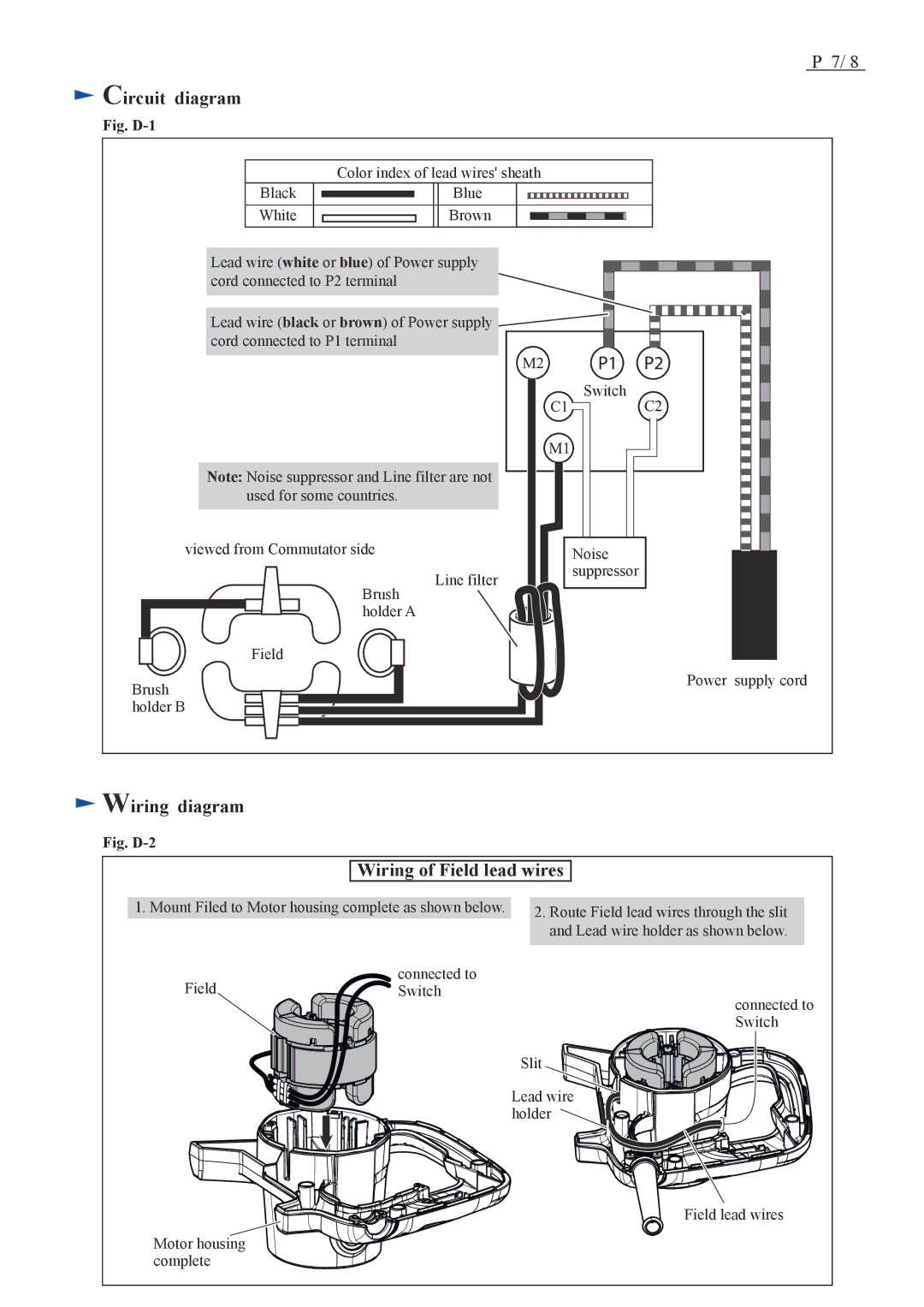
Lead wire (white or blue) of Power supply cord connected to P2 terminal
Lead wire (black or brown) of Power supply cord connected to P1 terminal
Note: Noise suppressor and Line filter are not used for some countries.
Switch |
viewed from Commutator side
Brush holder A
Field
Brush holder B
Line filter
Noise |
suppressor |
Power supply cord
 Wiring diagram
Fig. D-2
Wiring of Field lead wires
1. Mount Filed to Motor housing complete as shown below.
Field | connected to |
Switch |
Motor housing complete
2.Route Field lead wires through the slit and Lead wire holder as shown below.
connected to Switch
Slit
Lead wire ![]()
![]()
![]()
![]()
![]()
![]()
![]()
![]() holder
holder ![]()
![]()
![]()
![]()
![]()
![]()
![]()
![]()
![]()
![]()
Field lead wires
