P 8/ 8
 Wiring diagram
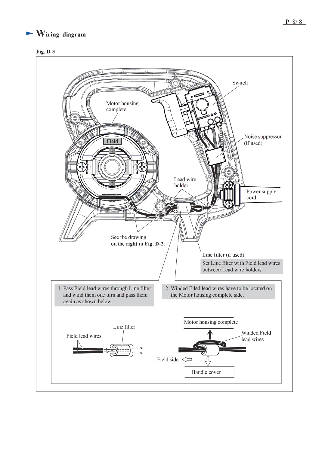
Fig. D-3
Switch
Motor housing complete
Field |
Noise suppressor (if used)
Lead wire holder
Power supply cord
See the drawing
on the right in Fig. D-2.
Line filter (if used)
1.Pass Field lead wires through Line filter and wind them one turn and pass them again as shown below.
Set Line filter with Field lead wires between Lead wire holders.
2.Winded Filed lead wires have to be located on the Motor housing complete side.
| Line filter | Motor housing complete |
|
Field lead wires |
| Winded Field | |
|
| ||
|
| lead wires | |
|
|
|
Field side
Handle cover