Prerequisites
When you replace the power supplies, remember to engage all of the safety features on each supply. The power supplies feature the following three safety interlock features:
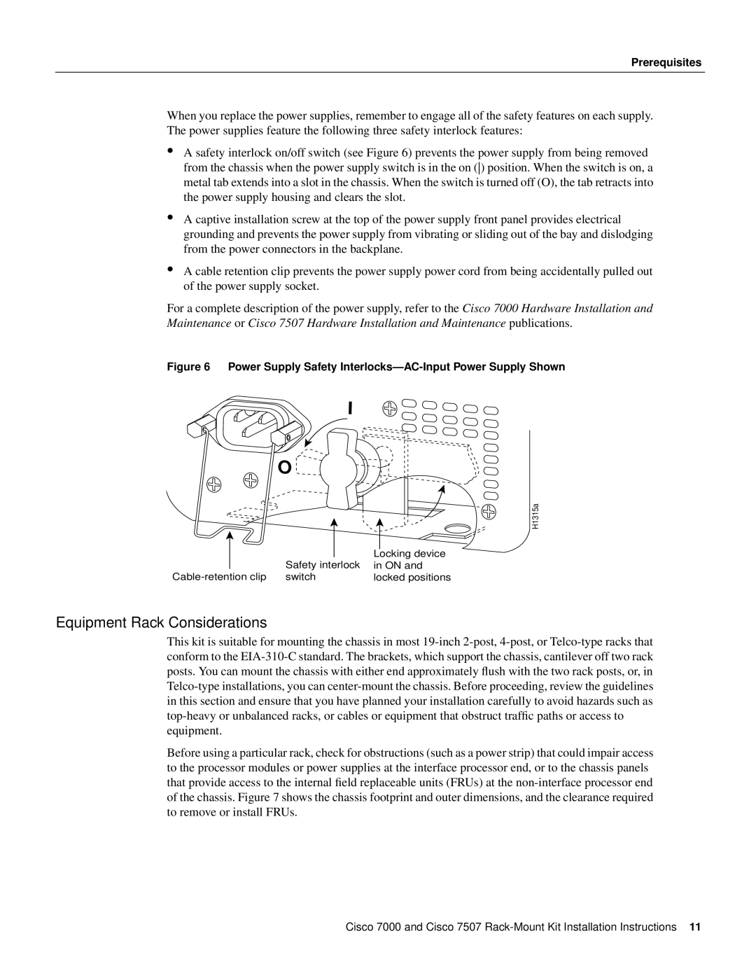
•A safety interlock on/off switch (see Figure 6) prevents the power supply from being removed from the chassis when the power supply switch is in the on () position. When the switch is on, a metal tab extends into a slot in the chassis. When the switch is turned off (O), the tab retracts into the power supply housing and clears the slot.
•A captive installation screw at the top of the power supply front panel provides electrical grounding and prevents the power supply from vibrating or sliding out of the bay and dislodging from the power connectors in the backplane.
•A cable retention clip prevents the power supply power cord from being accidentally pulled out of the power supply socket.
For a complete description of the power supply, refer to the Cisco 7000 Hardware Installation and Maintenance or Cisco 7507 Hardware Installation and Maintenance publications.
Figure 6 Power Supply Safety Interlocks—AC-Input Power Supply Shown
I
O
H1315a
|
| Safety interlock | Locking device |
|
| in ON and | |
switch | locked positions | ||
Equipment Rack Considerations
This kit is suitable for mounting the chassis in most
Before using a particular rack, check for obstructions (such as a power strip) that could impair access to the processor modules or power supplies at the interface processor end, or to the chassis panels that provide access to the internal field replaceable units (FRUs) at the
Cisco 7000 and Cisco 7507