Cisco Systems Cisco 7507, Cisco 7000 Shows the components in this mounting kit

Models: Cisco 7507 Cisco 7000

1 38
Download 38 pages 54.71 Kb
Page 4
Image 4

Rack-Mount Kit Overview

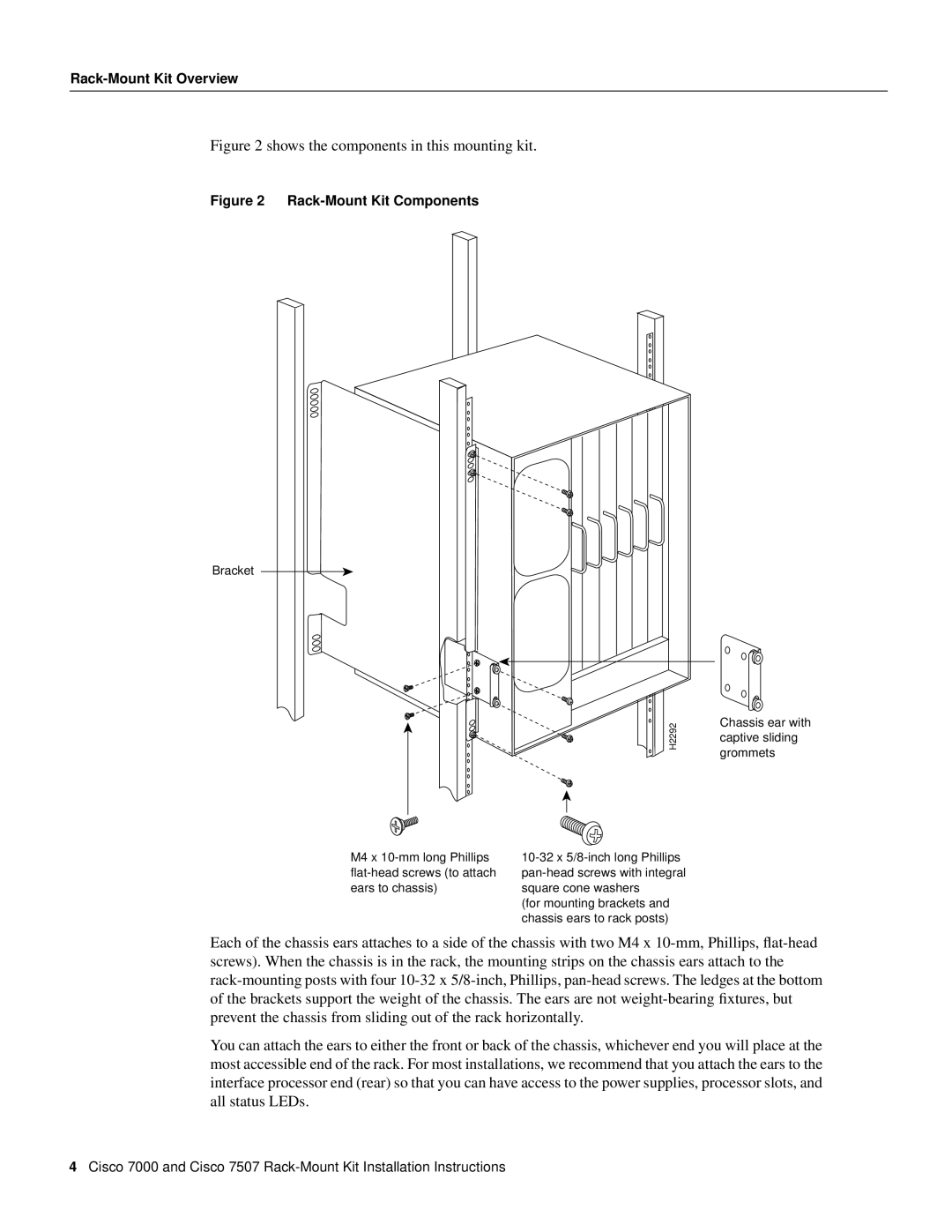
Figure 2 shows the components in this mounting kit.

Figure 2 Rack-Mount Kit Components

Bracket

H2292

M4 x 10-mm long Phillips

10-32 x 5/8-inch long Phillips

flat-head screws (to attach

pan-head screws with integral

ears to chassis)

square cone washers


(for mounting brackets and


chassis ears to rack posts)

Chassis ear with captive sliding grommets

Each of the chassis ears attaches to a side of the chassis with two M4 x 10-mm, Phillips, flat-head screws). When the chassis is in the rack, the mounting strips on the chassis ears attach to the rack-mounting posts with four 10-32 x 5/8-inch, Phillips, pan-head screws. The ledges at the bottom of the brackets support the weight of the chassis. The ears are not weight-bearing fixtures, but prevent the chassis from sliding out of the rack horizontally.

You can attach the ears to either the front or back of the chassis, whichever end you will place at the most accessible end of the rack. For most installations, we recommend that you attach the ears to the interface processor end (rear) so that you can have access to the power supplies, processor slots, and all status LEDs.

4Cisco 7000 and Cisco 7507 Rack-Mount Kit Installation Instructions

Page 4
Image 4
Cisco Systems Cisco 7507, Cisco 7000 installation instructions Shows the components in this mounting kit