Attaching the Chassis Ears
The ears attach directly to the chassis with four M4 x 10-mm, flat-head screws. Attach the ears to the chassis before you slide the chassis onto the brackets and back into the rack. After you slide the chassis into the rack, insert a 10-32 x 5/8-inch pan-head screw through each of the captive grommets on the ears and through the rack-mounting strips. The ears do not bear the weight of the chassis, but prevent it from walking, or sliding horizontally out of the rack.
You can mount the ears on either the front or rear of the chassis, whichever end will be in the front of the rack. We recommend that you attach them to the interface processor end of the chassis, so the power supplies and processor modules will be accessible at the front of the rack.
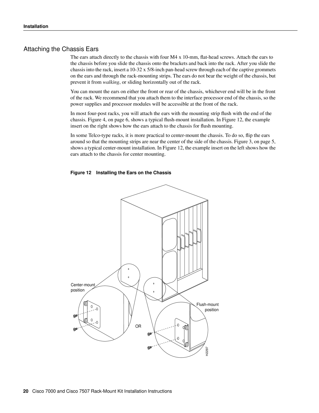
In most four-post racks, you will attach the ears with the mounting strip flush with the end of the chassis. Figure 4, on page 6, shows a typical flush-mount installation. In Figure 12, the example insert on the right shows how the ears attach to the chassis for flush mounting.
In some Telco-type racks, it is more practical to center-mount the chassis. To do so, flip the ears around so that the mounting strips are near the center of the side of the chassis. Figure 3, on page 5, shows a typical center-mount installation. In Figure 12, the example insert on the left shows how the ears attach to the chassis for center mounting.
Figure 12 Installing the Ears on the Chassis
Center-mount position
Flush-mount position
OR

 H2297
H2297
20Cisco 7000 and Cisco 7507 Rack-Mount Kit Installation Instructions