Installation
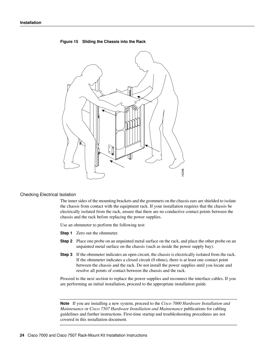
Figure 15 Sliding the Chassis into the Rack
H2298
Checking Electrical Isolation
The inner sides of the mounting brackets and the grommets on the chassis ears are shielded to isolate the chassis from contact with the equipment rack. If your installation requires that the chassis be electrically isolated from the rack, ensure that there are no conductive contact points between the chassis and the rack before replacing the power supplies.
Use an ohmmeter to perform the following test:
Step 1 Zero out the ohmmeter.
Step 2 Place one probe on an unpainted metal surface on the rack, and place the other probe on an unpainted metal surface on the chassis (such as inside the power supply bay).
Step 3 If the ohmmeter indicates an open circuit, the chassis is electrically isolated from the rack. If the ohmmeter indicates a closed circuit (0 ohms), there is at least one contact point between the chassis and the rack. Do not install the power supplies until you locate and resolve all points of contact between the chassis and the rack.
Proceed to the next section to replace the power supplies and reconnect the interface cables. If you are performing an initial installation, proceed to the appropriate installation guide.
Note If you are installing a new system, proceed to the Cisco 7000 Hardware Installation and Maintenance or Cisco 7507 Hardware Installation and Maintenance publications for cabling guidelines and further instructions.
24Cisco 7000 and Cisco 7507