CDR510 specifications
The Marantz CDR510 is a highly regarded CD recorder that combines advanced technology with user-friendly features for audiophiles and music enthusiasts. It gained recognition for its ability to deliver exceptional sound quality while providing a range of functionalities that cater to both recording and playback needs.One of the standout characteristics of the CDR510 is its dual functionality as both a CD recorder and a CD player. This versatility allows users to easily record their favorite music from various sources including vinyl records, cassette tapes, and other audio devices directly onto CD-R or CD-RW discs. The inclusion of a high-quality analog-to-digital converter ensures that recordings capture the nuanced details of the original audio source, resulting in an accurate and high-fidelity reproduction.
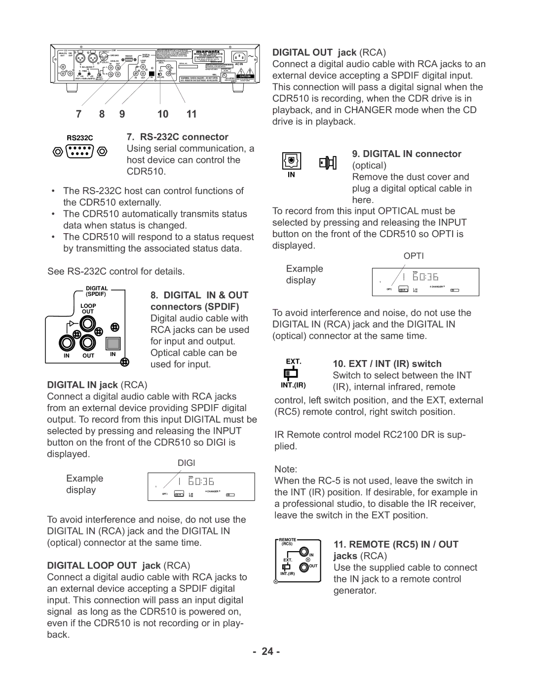
The CDR510 also features a digital input/output, allowing for greater connectivity options. Users can connect external sources such as digital audio players or computers via optical or coaxial connections, making it a flexible choice for those looking to integrate this recorder into their existing audio setups. Enhanced functionality is provided through a variety of playback modes, including repeat and shuffle, allowing users to customize their listening experience.
Another notable technology in the CDR510 is its built-in sampling rate converter, which enables the recording of audio from sources with different sample rates, ensuring compatibility and high-quality playback regardless of the origin of the material. The device supports CD-R and CD-RW formats, providing users with the flexibility to choose between permanent and erasable recording options.
The user interface of the Marantz CDR510 is intuitive, featuring a clear display that provides essential information about the current track, elapsed time, and remaining time, making navigation straightforward for users. The front panel controls are well laid out, ensuring ease of access to various functions, from recording to editing tracks.
Overall, the Marantz CDR510 is an exceptional CD recorder that embodies the brand’s commitment to audio quality and user satisfaction. With a combination of versatile recording capabilities, high-quality audio processing, and user-friendly design, it remains a popular choice for those who value both music preservation and playback excellence. Whether you're looking to archive your music collection or create custom mixes, the CDR510 provides a reliable and high-performance solution.

